- 6 -
turning it on again, remove the broken components and the ones that cause
overloading, then replace the fuse.
•
The 1st, 2nd, 3rd and 4th zones also have a joint potential-free connection
point that controls the boiler (NO
-
COM).
These connection points clamp
shut following the heating command of any of the four thermostats, and this
starts the boiler.
•
The
NO
-
COM
,
Z1-2
,
Z3-4
,
Z1-4
outputs of the zone controller are equipped
with delay functions, see Section
5
for more information.
3. LOCATION OF THE DEVICE
It is reasonable to locate the zone controller near the boiler and/or the manifold
in a way, so that it is protected from dripping water, dusty and chemically
aggressive environment, extreme heat and mechanical damage.
4. INSTALLING THE ZONE CONTROLLER AND PUTTING IT
INTO OPERATION
Attention!
The device must be installed and connected by a qualified
professional! Before putting the zone controller into operation make sure that
neither the zone controller nor the apparatus to be connected to it is connected
to the 230 V mains voltage. Modifying the device can cause electric shock or
product failure.
Attention!
We recommend that you design the heating system you want to
control with the
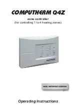
COMPUTHERM
Q4Z
zone controller so that the heating medium
can circulate in the closed position of all zone valves when a circulating pump
is switched on. This can be done with a permanently open heating circuit or by
installing a by-pass valve.
Attention!
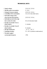
In switched on state 230 V AC voltage appears on the zone outputs,
the maximum loadability is 2 A (0,5 A inductive). This information should be
considered at the installation.
The size of the connection points of the
COMPUTHERM
Q4Z
zone controller
allow at most 2 or 3 devices to be connected in parallel to any heating zone.
If more than this is needed for any of the heating zones (e.g. 4 zone valves),
then the wires of the devices should be joined before they are connected to the
zone controller.
To install the zone controller, follow these steps:
•
Detach the rear panel of the device from its front panel by loosening the
screws at the bottom of the cover. By this, the connection points of the
Summary of Contents for Q4Z
Page 1: ...Operating Instructions zone controller for controlling 1 to 4 heating zones COMPUTHERM Q4Z...
Page 2: ......
Page 11: ......

