


BrandMe
Security Floor Stand
User Manual
©Compulocks Brands Inc. All Rights Reserved.
www.compulocks.com | [email protected] | +1 800-948-0344
Page 1 of 10
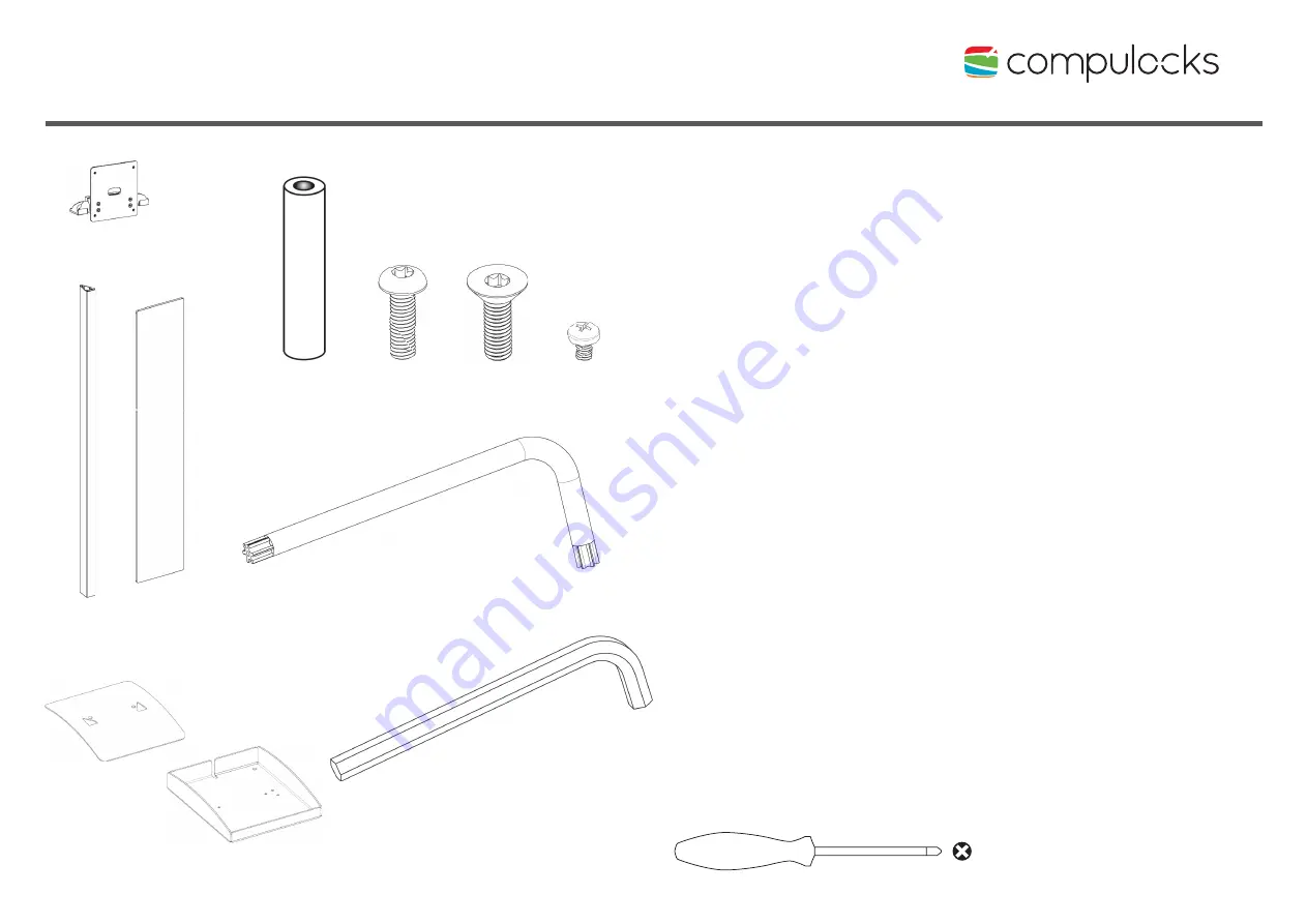
A
Top End Assembly
B
Upright Extrusion
C
Graphic Panel
D
Base Cover
E
Base
F
M5 x 40mm Round Spacer
G
M5 x 20mm Button Head Screw
H
M5 x 20mm Flat Head Screw
I
M4 x 8mm Button Head Phillips Screw
J
T-25 Torx L-Wrench
K
M5 Hex Wrench
A
x1
x2
x1
x1
x2
x1
x1
x4
x8
x4
B
C
D
F
G
H
I
J
K
x1
E
NOTE!
Before getting started
If you plan on a constant power connection to
your Tablet, you will need to obtain a longer USB
cable, allowing you to route the cable through
the Upright Extrusion (B).
You will also need a AC Power Cord to connect
to a Power Cube. These Cables are not supplied
with the Stand.
To attach Enclosure to the Top End Assembly you
will need Phillips Head Screwdriver.