Compex WP54G 1a User Manual Download Page 29

Access to Web-based Interface 


18 


S

S

t

t

e

e

p

p


5

5

:

:


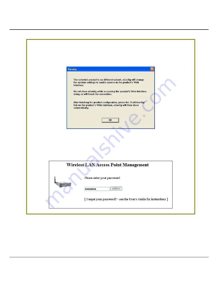
Do not exit the uConfig program while accessing to the web-based interface. 

This will disconnect you from the device. Click on the 

O

O

K

K

 button to proceed. 


S

S

t

t

e

e

p

p


6

6

:

:


At the login page, press the 

L

L

O

O

G

G

I

I

N

N

!

!

 button to enter the configuration page. 

The default password is “password”. 


Summary of Contents for WP54G 1a

Page 1: ......

Page 2: ...laws Manual Revision by Ann Manual Number U 0478 V1 1C Version 1 1 November 2005 Disclaimer Compex Inc provides this manual without warranty of any kind either expressed or implied including but not...

Page 3: ...help Caution Any changes or modifications not expressly approved by the grantee of this device could void the user s authority to operate the equipment FCC Compliance Statement This device complies w...

Page 4: ...24 IEC61000 4 2 3 4 5 6 8 11 Low Voltage Directive EN 60 950 1992 A1 1993 A2 1993 A3 1995 A4 1996 A11 1997 Therefore this product is in conformity with the following regional standards FCC Class B fol...

Page 5: ...port Centres Contact the technical support centre that services your location U S A Canada Latin America and South America Write Compex Inc 840 Columbia Street Suite B Brea CA 92821 USA Call Fax Tel T...

Page 6: ...luded in this document However for other operating system you may need to refer to your operating system s documentation for networking How to Use this Document This document may become superseded in...

Page 7: ...ection concerns risk of injury system damage or loss of data WARNING This section concerns risk of severe injury References on Menu Command Push Button Radio Button LED and Label appear in Bold For ex...

Page 8: ...to use which mode 3 Access Point Mode 4 Access Point Client Mode 5 Point to Point Mode 6 Point to Multiple point Mode 7 Wireless Routing Client Mode 8 Gateway Mode 9 CHAPTER 2 HARDWARE INSTALLATION 1...

Page 9: ...and Point to Multiple Point modes 62 MAC Filtering 67 CHAPTER 5 WLAN SECURITY 71 How to set up WEP 72 How to set up WPA PSK WPA2 PSK WPA PSK AUTO Only available in Access Point mode 73 How to set up 8...

Page 10: ...atic Address Translation only supported by Wireless Routing Client and Gateway 111 DNS Redirection only supported by Wireless Routing Client and Gateway 113 To enable disable DNS Redirection 115 Dynam...

Page 11: ...Get Technical Support 142 About System 143 APPENDIX I FIRMWARE RECOVERY 144 APPENDIX II TCP IP CONFIGURATION 146 For Windows 95 98 98SE ME NT 146 For Windows XP 2000 149 APPENDIX III PANEL VIEWS DESC...

Page 12: ...r your network Moreover its integrated Power over Ethernet PoE allows the access point to be used in areas where power outlets are not readily available To protect your security and privacy the access...

Page 13: ...s PCs and enhancing the privacy of the wireless clients This is especially useful in public hotspot deployment H Hi ig gh hl ly y S Se ec cu ur re ed d W Wi ir re el le es ss s N Ne et tw wo or rk k T...

Page 14: ...a retail package contains the following items 1 x Compex WP54G 1a 1 x External Power Adapter 1 x 2dBi SMA Antenna 1 x Read Me First Note 1 x Product CD W WH HE EN N T TO O U US SE E W WH HI IC CH H M...

Page 15: ...access point The Access Point mode enables you to bridge wireless clients to access the wired network infrastructure and to communicate with each other In the example above the wireless users will be...

Page 16: ...wireless client that can operate wirelessly with another access point to perform bridging between two Fast Ethernet networks The Access Point client cannot communicate directly with any other wireles...

Page 17: ...t to point communication between different buildings It enables you to bridge wireless clients that are kilometres apart eg within 100 metres between two buildings while unifying the networks In the e...

Page 18: ...le Point mode this mode is similar to that of the Point to Point mode But the access point located at one facility is able to connect to up to 15 access points AP installed in any direction from that...

Page 19: ...tion of this mode would be for the Ethernet port of the Wireless Routing Client to be used for connection with other devices on the network while access to the Internet would be achieved through wirel...

Page 20: ...nection if you have subscribed to a fixed IP address or to a range of fixed IP addresses from your Internet Service Provider Dynamic IP address When powered using this type of connection the access po...

Page 21: ...in Germany which uses T 1 connection or If you are using SingNet Broadband or Pacific Internet Broadband in Singapore PPTP Select this type of connection if you are using ADSL services in a country u...

Page 22: ...nodes H HA AR RD DW WA AR RE E I IN NS ST TA AL LL LA AT TI IO ON N The access point can be powered using either the power adapter provided or the Compex PoE Injector The installation process for both...

Page 23: ...the socket of the access point S St te ep p 4 4 Turn ON the power supply and power ON your PC Notice that the LEDs Power and Port 1 or 2 depending on which port you have connected the RJ45 Ethernet ca...

Page 24: ...e already purchased the Compex PoE and who wish to use it to supply power to the access point may follow the installation procedures shown below S St te ep p 1 1 Connect the external antenna to the SM...

Page 25: ...the PoE Injector s RJ45 Ethernet cable to your network device such as to a switch or hub S St te ep p 4 4 Connect the power adapter supplied in the Compex PoE kit to the main electrical supply and th...

Page 26: ...EDs Power and Port 1 or 2 depending on which port you have connected the PoE injector to have lighted up This indicates that the access point is receiving power through the PoE Injector and that conne...

Page 27: ...in n t th he e a ad dd dr re es ss s b ba ar r o of f I In nt te er rn ne et t E Ex xp pl lo or re er r You need to assign an IP address to your PC such as 192 168 168 x where x can take any value fro...

Page 28: ...owing screen will appear click on the Y Ye es s button to proceed S St te ep p 4 4 Select N Ne et tP Pa as ss sa ag ge e W WP P5 54 4G G in the C Co om mp pe ex x P Pr ro od du uc ct ts s L Li is st t...

Page 29: ...onfig program while accessing to the web based interface This will disconnect you from the device Click on the O OK K button to proceed S St te ep p 6 6 At the login page press the L LO OG GI IN N but...

Page 30: ...Access to Web based Interface 19 S St te ep p 7 7 You will then reach the home page of your access point s web based interface...

Page 31: ...am NpFind intended to help you verify the IP address of your Compex product Follow the next steps to check the IP address of your access point S St te ep p 1 1 Insert the Product CD into the CD ROM dr...

Page 32: ...PC so that it belongs to the same subnet as your access point In this example we are using Windows XP for illustration For Windows 98 98SE 2000 NT ME kindly refer to Appendix II TCP IP Configuration...

Page 33: ...r ro op pe er rt ti ie es s button S St te ep p 4 4 Select the radio button for U Us se e t th he e f fo ol ll lo ow wi in ng g I IP P a ad dd dr re es ss s Enter the IP Address and Subnet Mask as 192...

Page 34: ...as been correctly assigned to your PC go to S St ta ar rt t menu A Ac cc ce es ss so or ri ie es s select C Co om mm ma an nd d P Pr ro om mp pt t and type the command ipconfig all Your PC is now read...

Page 35: ...t ti in ng gs s section disable all the option boxes Click on the O OK K button to update the changes S St te ep p 9 9 At the A Ad dd dr re es ss s bar enter http 192 168 168 1 and press E En nt te er...

Page 36: ...Access to Web based Interface 25 You will then reach the home page of your access point s Web interface...

Page 37: ...a an na ag ge em me en nt t P Po or rt t W WL LA AN N B Ba as si ic c S Se et tu up p W WL LA AN N S Se ec cu ur ri it ty y S ST TP P S Se et tu up p S SN NM MP P M MA AC C F Fi il lt te er ri in ng g...

Page 38: ...1 1 Click on M Ma an na ag ge em me en nt t P Po or rt t from the C CO ON NF FI IG GU UR RA AT TI IO ON N menu In the M Ma an na ag ge em me en nt t P Po or rt t S Se et tu up p page refer to the tabl...

Page 39: ...e LAN you can set the IP address of the access point as the Management Gateway IP The Management Gateway IP address of your access point is set to nil by default The next two fields DHCP Start IP Addr...

Page 40: ...o an Internet gateway X a PC wired to the access point will be unable to obtain a dynamic IP address directly from X But if you can enable the DHCP server of the access point and set the IP address of...

Page 41: ...dv va an nc ce ed d D DH HC CP P S Se er rv ve er r O Op pt ti io on ns s section click on the S Sh ho ow w A Ac ct ti iv ve e D DH HC CP P l le ea as se es s button The DHCP Active Leases table disp...

Page 42: ...ddress allocation For instance if you set up a publicly accessible FTP HTTP server within your private LAN while that server would require a fixed IP address you would still want the DHCP server to dy...

Page 43: ...ess to reserve The Hardware Address in pairs of two hex values Press the A Ap pp pl ly y button to make your new entry effective The D DH HC CP P S Se er rv ve er r R Re es se er rv va at ti io on ns...

Page 44: ...reserve an IP address anymore you can delete the DHCP Server Reservation S St te ep p 1 1 Click on the reserved IP address that you wish to delete e g 192 168 168 20 S St te ep p 2 2 Click on the D De...

Page 45: ...ter 5 on WLAN Security for details Advanced This function furthers the basic configuration of the access point by setting the system s additional parameters Wireless Pseudo VLAN WDS Configuration and...

Page 46: ...will see the sub menus expanded under W WL LA AN N S Se et tu up p Click on B Ba as si ic c The default operating mode of Access point is the Access Point mode S St te ep p 2 2 O Op pt ti io on na al...

Page 47: ...our changes take effect Note that the W WL LA AN N B Ba as si ic c S Se et tu up p page for the Client mode is different from that of the Access Point mode If you wish to set the access point in the P...

Page 48: ...n nt t t to o M Mu ul lt ti ip pl le e P Po oi in nt t and then you will see the page below To create a new peer MAC click on the P Pe ee er r M MA AC C L Li is st t button The page will appear Please...

Page 49: ...s clients must be configured with the same ESSID This case sensitive entry can consist of a maximum of 32 characters Site Survey A list of wireless devices that are detected by your access point in th...

Page 50: ...ple Point mode This mode can support up to 15 access points This feature allows you to create up to 15 peer MAC addresses so that the router can connect to this number of the access points Country Cho...

Page 51: ...D DE E S St te ep p 1 1 In the M Mo od de e S Se et tu up p page click on the S Si it te e S Su ur rv ve ey y button The S Si it te e S Su ur rv ve ey y provides a list of the M MA AC C a ad dd dr re...

Page 52: ...neighbouring access points that can be viewed from the Site Survey page Parameters Description Bssid In an infrastructure wireless network the BSSID refers to the wireless MAC address of the access po...

Page 53: ...wing information supplied by the Site Survey according to the security setting is explained If the security mode is set to None or WEP the scan will show all available access points that have no secur...

Page 54: ...nk k I In nf fo or rm ma at ti io on n button The L Li in nk k I In nf fo or rm ma at ti io on n table illustrates the following data This table describes the parameters that can be viewed from the L...

Page 55: ...E ED D S SE ET TU UP P O OF F T TH HE E W WI IR RE EL LE ES SS S M MO OD DE E The following will guide you to configure the advanced setup of the wireless mode you have selected S St te ep p 1 1 Click...

Page 56: ...how often the beacon contains a delivery traffic indication message DTIM The DTIM identifies which clients in power save mode have data frames waiting for them in the access point s buffer If the bea...

Page 57: ...device that is connected to the WLAN I IN N A AC CC CE ES SS S P PO OI IN NT T M MO OD DE E S St te ep p 1 1 Click on W WL LA AN N S Se et tu up p from the C CO ON NF FI IG GU UR RA AT TI IO ON N men...

Page 58: ...figuration 47 S St te ep p 3 3 To check the details on individual wireless client click on the MAC Address in the WLAN Station List The following screen will show the statistics of the selected wirele...

Page 59: ...F FI IG GU UR RA AT TI IO ON N menu You will see the sub menus expanded under W WL LA AN N S Se et tu up p Click on S St ta at ti is st ti ic cs s In C Cl li ie en nt t mode you are not allowed to vie...

Page 60: ...F FI IG GU UR RA AT TI IO ON N menu You will see the sub menus expanded under W WL LA AN N S Se et tu up p Click on S St ta at ti is st ti ic cs s In P Po oi in nt t t to o P Po oi in nt t mode you ar...

Page 61: ...F FI IG GU UR RA AT TI IO ON N menu You will see the sub menus expanded under W WL LA AN N S Se et tu up p Click on S St ta at ti is st ti ic cs s In P Po oi in nt t t to o M Mu ul lt ti ip pl le e P...

Page 62: ...F FI IG GU UR RA AT TI IO ON N menu You will see the sub menus expanded under W WL LA AN N S Se et tu up p Click on S St ta at ti is st ti ic cs s In W Wi ir re el le es ss s R Ro ou ut ti in ng g C C...

Page 63: ...F FI IG GU UR RA AT TI IO ON N menu You will see the sub menus expanded under W WL LA AN N S Se et tu up p Click on S St ta at ti is st ti ic cs s In G Ga at te ew wa ay y mode you are not allowed to...

Page 64: ...your ISP provides you with a fixed WAN IP address or a range of fixed IP addresses refer to WAN Setup Cable Internet with Static IP Assignment ADSL Internet that requires standard PPP over Ethernet P...

Page 65: ...e effect Note There are exceptional cases where additional configuration is required before an IP address will be allocated by your ISP to the access point a Certain ISPs log the MAC address of the fi...

Page 66: ...e button so that your access point clones the ISP recognized MAC address of your Ethernet adapter Please remember to click R Re eb bo oo ot t S Sy ys st te em m under S SY YS ST TE EM M T TO OO OL LS...

Page 67: ...ey in a preferred S Sy ys st te em ms s C Co on nt ta ac ct t person and the S Sy ys st te em m L Lo oc ca at ti io on n of the access point Click the A Ap pp pl ly y button to complete Please remembe...

Page 68: ...d menu click on W WA AN N S Se et tu up p Step 2 Access the S Se el le ec ct t W WA AN N T Ty yp pe e page and choose S St ta at ti ic c I IP P A Ad dd dr re es ss s before clicking the A Ap pp pl ly...

Page 69: ...t W WA AN N T Ty yp pe e page and choose P PP PP P o ov ve er r E Et th he er rn ne et t before clicking the A Ap pp pl ly y button You will then be brought to the following page requiring your inputs...

Page 70: ...uthentication you can set up your access point s WAN type from the steps that follow For example if the ISP provided you with the following set up information you can set up your WAN as described belo...

Page 71: ...to let the settings take effect The I Id dl le e T Ti im me eo ou ut t setting allows you to specify the value in seconds after which the access point will disconnect from the ISP after the last Inte...

Page 72: ...ure of the hardware devices Step 1 Click on S SN NM MP P from the C CO ON NF FI IG GU UR RA AT TI IO ON N menu Step 2 Select E En na ab bl le e from the S SN NM MP P S St ta at te e drop down list The...

Page 73: ...PL LE E P PO OI IN NT T M MO OD DE ES S Spanning Tree Protocol STP is a link management protocol that helps to prevent undesirable loops occurs in the network For an Ethernet network to function prope...

Page 74: ...nks as a backup in case the active link should fail If STP costs change or if one network segment in the STP becomes unreachable the spanning tree algorithm reconfigures the spanning tree topology and...

Page 75: ...te scenarios Scenario 1 No STP No Pseudo VLAN Referring to the illustration below if the Spanning Tree Protocol STP and Pseudo VLAN are not implemented in a network all clients Notebook 1 2 3 4 can ac...

Page 76: ...ed hence preventing multiple active network paths in between any two APs If one of the APs is down the STP algorithm will reactivate one of the redundant paths so that the network connection will not...

Page 77: ...seudo VLAN Per Node is activated the wireless users will be unable to access one another S St te ep p 1 1 Click on S ST TP P S Se et tu up p from the C CO ON NF FI IG GU UR RA AT TI IO ON N menu S St...

Page 78: ...ress corresponding to users who are allowed to access the network or to keep a list of MAC address corresponding to users who are forbidden from network access S St te ep p 1 1 Click on M MA AC C F Fi...

Page 79: ...d dr re es ss s you just added Click on the A Ap pp pl ly y button Notice that the MAC Address has been added to the list S St te ep p 4 4 Next you can choose whether you wish to allow or to prevent n...

Page 80: ...L LI IS ST T Follow the procedures mentioned in Step 2 to Step 3 E ED DI IT T D DE EL LE ET TE E A A M MA AC C A AD DD DR RE ES SS S F FR RO OM M T TH HE E M MA AC C A AD DD DR RE ES SS S L LI IS ST T...

Page 81: ...tion 70 S St te ep p 2 2 From the E Ed di it t M MA AC C A Ad dd dr re es ss s page Click on the D De el le et te e button to remove the MAC address or Click on the S Sa av ve e button after you have...

Page 82: ...t with follow the common preliminary steps described below to select the most appropriate security approach for protecting your wireless communications S St te ep p 1 1 Click on W WL LA AN N S Se et t...

Page 83: ...ting either U Us se e H He ex xa ad de ec ci im ma al l U Us se e A AS SC CI II I S St te ep p 2 2 Select the T Tr ra an ns sm mi is ss si io on n K Ke ey y from the pull down menu K Ke ey y 1 1 K Ke...

Page 84: ...he R Re es se et t button Click on the A Ap pp pl ly y button and reboot your access point H HO OW W T TO O S SE ET T U UP P W WP PA A P PS SK K W WP PA A2 2 P PS SK K W WP PA A P PS SK K A AU UT TO O...

Page 85: ...pe e to T TK KI IP P WPA replaces WEP with a strong encryption technology called Temporal Key Integrity Protocol TKIP with Message Integrity Check MIC For WPA2 PSK Set the C Ci ip ph he er r T Ty yp...

Page 86: ...x RADIUS At the IEEE 802 1x Setup page S St te ep p 1 1 Key in the IP address of the P Pr ri im ma ar ry y R RA AD DI IU US S S Se er rv ve er r in your WLAN You can optionally add in the IP address o...

Page 87: ...K Ke ey y in the field provided S St te ep p 5 5 By default the B Br ro oa ad dc ca as st t K Ke ey y R Ro ot ta at ti io on n is set as 6 60 00 0 seconds You may leave this value as its default sett...

Page 88: ...At the W WP PA A1 1 2 2 E EA AP P S Se et tu up p page S St te ep p 1 1 Key in the IP address of the P Pr ri im ma ar ry y R RA AD DI IU US S S Se er rv ve er r in your WLAN You can optionally add in...

Page 89: ...28 8 b bi it t 26 hexadecimal or 13 ASCII Text S St te ep p 6 6 For WPA EAP Set the C Ci ip ph he er r T Ty yp pe e to T TK KI IP P WPA replaces WEP with a strong encryption technology called Temporal...

Page 90: ...the length of time after which the access point will automatically generate a new shared key to secure multicast broadcast traffic among all stations that are communicating with it By default the valu...

Page 91: ...etwork segment although they may be physically located on different segments of a LAN Those stations which are assigned to the same VLAN share network resources and bandwidth as if they were connected...

Page 92: ...E EU UD DO O V VL LA AN N P PE ER R N NO OD DE E When implemented this mode isolates each wireless client into its own pseudo VLAN Wireless clients can therefore access resources on the wired network...

Page 93: ...LA AN N A Ad dv va an nc ce ed d S Se et tu up p page S St te ep p 2 2 Go to the E Ex xt te en nd de ed d F Fe ea at tu ur re es s section and click on the W Wi ir re el le es ss s P Ps se eu ud do o...

Page 94: ...Wireless Extended Features 83 S St te ep p 4 4 Select the P Pe er r n no od de e radio button and click on the A Ap pp pl ly y button The Wireless Pseudo VLAN has configured as Per node...

Page 95: ...f wireless clients identified by their MAC address Whenever a wireless client requests network access the access point will first verify whether its MAC address is present in any of the Pseudo VLAN gr...

Page 96: ...N N A A P PS SE EU UD DO O V VL LA AN N G GR RO OU UP P S St te ep p 1 1 From the S Se el le ec ct t W Wi ir re el le es ss s P Ps se eu ud do o V VL LA AN N T Ty yp pe e page select P Pe er r g gr ro...

Page 97: ...t x xx x x xx x x xx x x xx x x xx x x xx x where x is any value within the range 0 9 or a f S St te ep p 5 5 Click on the A Ad dd d button to update the changes The Pseudo VLAN group has been added t...

Page 98: ...IT T D DE EL LE ET TE E A A C CL LI IE EN NT T I IN N A A P PS SE EU UD DO O V VL LA AN N G GR RO OU UP P S St te ep p 1 1 Click on the M MA AC C a ad dd dr re es ss s in the table as shown below S S...

Page 99: ...of wired and wireless clients while at the same time connecting to other access points This requires the operational frequency channel to be the same within the cell controlled by your access point as...

Page 100: ...g corridor Satellite access points are chained together starting from a root access point The access point at either end of the chain will have only one WDS link enabled while the access points in the...

Page 101: ...figuration click on A Ad dv va an nc ce ed d which shows the W WL LA AN N A Ad dv va an nc ce ed d S Se et tu up p page S St te ep p 2 2 Go to the E Ex xt te en nd de ed d F Fe ea at tu ur re es s sec...

Page 102: ...utton S St te ep p 5 5 Click on the A Ad dd d button to create a MAC address of a client S St te ep p 6 6 Fill up the H Ha ar rd dw wa ar re e A Ad dd dr re es ss s field with the wireless MAC address...

Page 103: ...e as shown below NOTE To configure WDS all your access points must use the same channel and security mode and both access points at opposite ends of a WDS link must have each other s wireless MAC addr...

Page 104: ...S S St te ep p 1 1 Click on the M MA AC C a ad dd dr re es ss s in the table as shown below S St te ep p 2 2 From the E Ed di it t W WD DS S E En nt tr ry y page Click on the D De el le et te e butto...

Page 105: ...rtlessly between physically distant APs The following steps demonstrate how to configure the Long Distance Parameters S St te ep p 1 1 From W WL LA AN N S Se et tu up p under Configuration click on A...

Page 106: ...o oo or r feature is disabled by default Select E En na ab bl le e from the pull down menu S St te ep p 4 4 The access point can automatically calculate the values of the parameters to input based on...

Page 107: ...your access point and the remote access point It should be entered in meters Slot Time Time is slotted and each unit of time is called one slot time ACK Timeout This parameter determines the timeout a...

Page 108: ...han one access point Important You do NOT need to set any routing information if you are simply configuring the access point for broadband Internet sharing Improper routing configuration will cause un...

Page 109: ...With an understanding of how adding a static routing entry can facilitate a network setup such as the one described above here is how you may configure the access point Step 1 Under the C CO ON NF FI...

Page 110: ...ent PCs NAT is enabled by default Due to NAT computers in the private LAN behind the access point will not be directly accessible from the Internet However employing virtual Servers lets you host Inte...

Page 111: ...sing which port number Since any reply from Internet goes to the access point first the access point from the port number in the reply packet knows to which client to forward the reply If the access p...

Page 112: ...y wish to set up a DMZ host if you intend to use a special purpose Internet Service such as an online game for which no i NOTE 1 When you enable DMZ the Static IP Address configuration is recommended...

Page 113: ...private network If you require more information on this function please refer to the NAT Technology Primer on the Product CD Step 1 Under the C CO ON NF FI IG GU UR RA AT TI IO ON N command menu click...

Page 114: ...e LAN IP address of your server PC running within the private network Custom Server Server Type Define a name for the server type you wish to configure Protocol Select either TCP or UDP protocol type...

Page 115: ...s of ports are forwarded to defined computers in the private network If you require more information of its function please refer to the NAT Technology Primer on the Product CD Here are the steps to s...

Page 116: ...55 Step 4 Click the A Ad dd d button to continue Step 5 The I IP P F Fo or rw wa ar rd d E En nt tr ri ie es s page will reflect your new addition NOTE For step 3 above please ensure that you have su...

Page 117: ...cess point Step 1 Under the C CO ON NF FI IG GU UR RA AT TI IO ON N command menu click on R Re em mo ot te e M Ma an na ag ge em me en nt t and you will be brought to the following screen Step 2 By de...

Page 118: ...h aggregated bandwidth In the event of a particular broadband connection failing The access point in cascade will use the remaining functional broadband channels giving you an added peace of mind with...

Page 119: ...WDS or the access points are wired to each other Finally you are ready to access the web based configuration of each of your access point to enable the Parallel Broadband feature You will have to enab...

Page 120: ...ou by email when there is a change in the WAN IP address that was supplied to you earlier Step 1 Under the C CO ON NF FI IG GU UR RA AT TI IO ON N command menu click on W WA AN N P PP PP Po oE E S Se...

Page 121: ...mail account user s name that should be entered if authentication is required Password This is the mail account user s password that should be entered if authentication is required Email address of Se...

Page 122: ...your home network to the Internet is using an IP address of 192 168 168 1 You have enabled SAT on your router and want to access the Internet without changing the IP address of the notebook as you ha...

Page 123: ...es s command menu click on S St ta at ti ic c A Ad dd dr re es ss s T Tr ra an ns sl la at ti io on n Step 2 You may then choose to E En na ab bl le e or D Di is sa ab bl le e Static Address Translat...

Page 124: ...direction feature DNS requests from the LAN clients will be processed by Access point Unless in the access point s LAN Setup you have already assigned a specific DNS server which should always be used...

Page 125: ...on 114 NOTE For Internet access please do NOT leave the DNS Server field of the PC s TCP IP Properties blank Simply key in any legal IP address for it e g 10 10 10 10 even though you do not have the e...

Page 126: ...ate on the Internet It gets even more complicated when ISPs change your public IP address regularly as is the case when the Internet connection type is Dynamic IP or PPPoE with Dynamic IP If you are d...

Page 127: ...Fe ea at tu ur re es s command menu click on D Dy yn na am mi ic c D DN NS S S Se et tu up p Step 2 You may then choose to E En na ab bl le e or D Di is sa ab bl le e Dynamic DNS here followed by clic...

Page 128: ...ccount There are two DDNS providers that are pre defined for you Please note that you need to be connected to the Internet to register your DDNS account To select 2MyDNS Dynamic DNS Service Provider a...

Page 129: ...Exchanger field enter the Static WAN IP address of the mail server configured to handle email for your domain Select B Ba ac ck ku up p M Ma ai il l E Ex xc ch ha an ng ge er r to enable this service...

Page 130: ...Advanced Configuration 119...

Page 131: ...n N Na am me e Step 3 Select A Au ut to o D De et te ec ct t to let the DtDNS server learn your current WAN IP address Enter your DtDNS account U Us se er rn na am me e and P Pa as ss sw wo or rd d S...

Page 132: ...s from connecting to the Internet T TO O C CO ON NF FI IG GU UR RE E P PA AC CK KE ET T F FI IL LT TE ER RI IN NG G Step 1 Under the S Se ec cu ur ri it ty y C Co on nf fi ig gu ur ra at ti io on n co...

Page 133: ...xample BlockCS 4b From the IP Address drop down list select whether to apply the rule to A Range of IP addresses In this case you will have to define From which IP address To which IP address your ran...

Page 134: ...fields blank Here the rule will apply to all ports 4d From the Day of the Week drop down list select whether the rule should apply to A Range of days Here you will have to select From which day To wh...

Page 135: ...n nf fi ig gu ur ra at ti io on n table will then be updated Step 6 In this example let us say we would like to block an application called CS from all PCs any IP address within the network from Monda...

Page 136: ...ick on U UR RL L F Fi il lt te er ri in ng g Step 2 You may now define the U UR RL L F Fi il lt te er r T Ty yp pe e by clicking the C Ch ha an ng ge e button Step 3 Select B Bl lo oc ck k or A Al ll...

Page 137: ...F FI IG GU UR RE E S SP PI I F FI IR RE EW WA AL LL L The following steps explain the configuration of Compex s SPI firewall As incorrect configuration to the firewall can result in undesirable networ...

Page 138: ...e left will appear Rule Name Enter a unique name to identify this firewall rule Disposition Policy This parameter determines whether the packets obeying the rule should be accepted or denied by the fi...

Page 139: ...n Request Information that is from the ICMP data packet Information Reply Information that is from the ICMP data packet IGMP Types This IP protocol is used to establish host memberships in particular...

Page 140: ...port Users can either set a single port number or a range of port numbers Check Options This parameter refers to the options in the packet header The available selection options are abbreviated as fo...

Page 141: ...of data traffic the time the source and destination address port as well as the action taken by the SPI firewall You can choose which type of packets to log from the Firewall Configuration T TO O V V...

Page 142: ...nt can communicate ping with another network host This feature is available only for the Wireless Routing Client and Gateway modes Step 1 Select P Pi in ng g U Ut ti il li it ty y under the S SY YS ST...

Page 143: ...m I Id de en nt ti it ty y from the S SY YS ST TE EM M T TO OO OL LS S menu S St te ep p 2 2 Enter a unique name in the S Sy ys st te em m N Na am me e field S St te ep p 3 3 Fill in the name of a per...

Page 144: ...el le ec ct t t to o C Ch ha an ng ge e t th he e T Ti im me e Z Zo on ne e f fo or r t th he e R Ro ou ut te er r L Lo oc ca at ti io on n drop down list S St te ep p 3 3 E En na ab bl le e the Auto...

Page 145: ...the next steps You can check the types and version of your firmware by clicking on About System from the HELP menu To begin with ensure that you have downloaded the latest firmware onto your local har...

Page 146: ...the instructions given during the upgrading process S St te ep p 4 4 You need to reboot the system after the firmware upgrade NOTE The firmware upgrade process must NOT be interrupted otherwise the d...

Page 147: ...t settings R RE ES SE ET T Y YO OU UR R S SE ET TT TI IN NG GS S S St te ep p 1 1 Click on B Ba ac ck ku up p o or r R Re es se et t S Se et tt ti in ng gs s from the S SY YS ST TE EM M T TO OO OL LS...

Page 148: ...up p o or r R Re es se et t S Se et tt ti in ng gs s from the S SY YS ST TE EM M T TO OO OL LS S menu S St te ep p 2 2 If you want to back up the current settings of your access point onto your hard d...

Page 149: ...e et tt ti in ng gs s from the S SY YS ST TE EM M T TO OO OL LS S menu S St te ep p 2 2 If you want to store back the settings that you had previously saved click on the B Br ro ow ws se e button Proc...

Page 150: ...uire a system reboot before the new parameters can take effect S St te ep p 1 1 Click on R Re eb bo oo ot t S Sy ys st te em m from the S SY YS ST TE EM M T TO OO OL LS S menu S St te ep p 2 2 Click o...

Page 151: ...ge e P Pa as ss sw wo or rd d from the S SY YS ST TE EM M T TO OO OL LS S menu S St te ep p 2 2 Key in the C Cu ur rr re en nt t P Pa as ss sw wo or rd d The factory default is password Enter the n ne...

Page 152: ...the Web interface follow the next few steps S St te ep p 1 1 Click on L Lo og go ou ut t from the S SY YS ST TE EM M T TO OO OL LS S menu S St te ep p 2 2 Click the L LO OG GI IN N button to access yo...

Page 153: ...of Compex s technical support centres around the world S St te ep p 1 1 Click on G Ge et t T Te ec ch hn ni ic ca al l S Su up pp po or rt t from the H HE EL LP P menu The access point is a feature pa...

Page 154: ...ystem data when they are troubleshooting your configuration You can use the information displayed in this page to quickly find the data they need to resolve your system problem S St te ep p 1 1 Click...

Page 155: ...loader mode Blinks very fast Recovery in progress ON Successful recovery Blinks very slowly Before starting check the status of the diagnostic LED against the table above to confirm whether firmware f...

Page 156: ...overy folder of the Product CD S St te ep p 6 6 If you have downloaded a newer firmware and have saved it in your local hard disk as C WP54G WP54Axxx IMG then replace the command with this new path an...

Page 157: ...168 xxx and its subnet mask is 255 255 255 0 where xxx can be any number from 2 to 254 excluding 1 Simply follow the procedures stated below to configure the TCP IP settings of your PC F FO OR R W WI...

Page 158: ...IP Address and Subnet Mask as 192 168 168 X and 255 255 255 0 where X can be any number from 2 to 254 except for 1 In this example we are using 192 168 168 160 as the static IP Address S St te ep p 5...

Page 159: ...Configuration 148 menu select Run and enter the command winipcfg Select your respective Ethernet Adapter from the drop down list and click OK Now your PC is now ready to communicate with your access...

Page 160: ...te ep p 1 1 Go to your desktop right click on My Network Places icon and select Properties S St te ep p 2 2 Go to your network adapter icon right click and select to Properties S St te ep p 3 3 Highl...

Page 161: ...ber from 2 to 254 except for 1 In this example we are using 192 168 168 160 as the static IP Address S St te ep p 5 5 Click on OK to close all windows S St te ep p 6 6 Next in order to check if the IP...

Page 162: ...d up 1 LED Power Off No power is supplied to the device 2 LED Diagnostic Flashing Green This indicates the flash during the power up The LED will goes off when the diagnostic is passed Steady Green WA...

Page 163: ...ice and the network Flashing Green Activity is detected in the network 5 LED Port 1 2 LEDs Off No network connection Back View of Access Point Name Description 6 External Antenna 2dBi SMA antenna 7 Et...

Page 164: ...reset password press and hold the button for 5 seconds The DIAG light will flash fast for about 5 flashes sec before releasing the button To restore the factory default settings press and hold the bu...

Page 165: ...802 11b IEEE 802 11g Performance Network speeds dynamically shift between 1 2 5 5 11 12 18 24 36 48 54 Mbps Indoor 20 m 54 Mbps Outdoor 80 m 54 Mbps Frequency Range IEEE 802 11b IEEE 802 11g 2 4 2 48...

Page 166: ...ireless Features Wireless Distribution System WDS Long Distance Parameters Setup Wireless Pseudo VLAN Per Node Per Group Tagged VLAN Adjustable transmit power control in 1dB steps Antenna Detachable 2...

Page 167: ...Technical Specifications 156 Operating Temp Storage Temp Operating Humidity 15 C to 70 C 5 to 95 RH Humidity RH Relative Humidity Physical Dimensions 145mm x 132mm x 41mm H x W x D...

Reviews: