


4–10
SAN Switch Integrated/32 and Integrated/64 Installation and Hardware Guide
4–10
SAN Switch Integrated/32 and Integrated/64 Installation and Hardware Guide
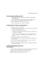
Configuring the Replacement Switch Element
To configure the replacement switch element:
1. Log on with administrative privileges to the new switch element, using a Telnet
connection.
2. Clear the configuration settings in the replacement switch element with the
cfgClear
command. The new switch element will acquire the configuration settings from the
other switches in the SAN once the Fibre Channel cables are reattached.
3. Replace the factory IP address with the address information used by the previous
switch.
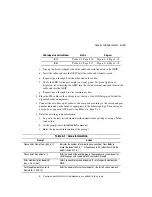
a. On the workstation, open a terminal emulation program such as HyperTerminal on
Windows 95 or NT, or TERM in a UNIX environment. Configure as shown in
Table 3–2, Page 3-5.
b. At the prompt, specify the new IP address by entering the
ipAddrSet
command. You
are prompted for the address configuration information shown in Step 3, Page 3-6.
c. Verify that the address was set correctly by entering the
IPaddressShow
command
.
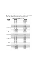
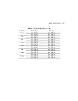
4. Set the Domain ID to the value used by the previous switch element, if still available.
The default Domain IDs on the six switch elements shipped with the SAN Integrated
Switch are 231, 232, 233, 234, 235 and 236, respectively.
NOTE:
If the Domain ID (whether the default or a selected ID) is already in use when the switch
a. Disable the switch element by entering the
switchDisable
command
.
b. Enter the
c. Enter
Y
after the prompt.
Fabric parameters (yes, y, no, n): [no] y.
d. Enter a unique Domain ID (such as the Domain ID used by the previous switch
element, if still available) at the prompt.
Domain: (1..239) [1] 3
.
e. Complete the remaining prompts (or press CTRL + D keys to accept the remaining
settings without completing all the prompts).
f. Enable the switch element by entering the
switchEnable
command.