


Configuring the SAN Integrated Switch
3–5
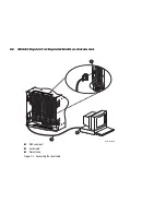
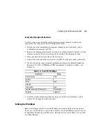
Connecting Through a Workstation
Use these steps to execute initial switch element operations through a workstation
connected to the serial port on the SAN Integrated Switch.
1. Disable any serial communication programs running on the workstation, such as
synchronization programs for PDA.
2. Remove the shipping plug from the serial port on switch element #1 (left-most switch
element), and insert the serial cable provided with the SAN Integrated Switch.
3. Insert one end of the serial cable into the serial port.
4. Connect the other end of the serial cable to an RS-232 serial port on the workstation.
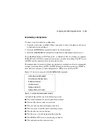
5. On the workstation, open a terminal emulation program such as HyperTerminal on
Windows 95 or NT, or TERM in a UNIX environment. Configure as follows (see
Table 3–2).
6. From the terminal emulator application, log on to the first switch element (switch
element #1) through the serial connection.
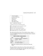
Setting the IP Address
Each switch element must have a valid IP address to enable an IP/network connection.
You can set two IP addresses: one for the external, out-of-band Ethernet port and one for
in-band Fibre Channel network (IP) access. In-band network access allows you to use IP
over Fibre Channel.
Table 3–2: Serial Port Settings
Parameter
Value
Bits per second
9600
Databits
8
Parity
None
Stop bits
1
Flow control
None
Function arrows and Ctrl keys act as:
Terminal Keys
Emulation
Autodetect