


3–6
SAN Switch Integrated/32 and Integrated/64 Installation and Hardware Guide
3–6
SAN Switch Integrated/32 and Integrated/64 Installation and Hardware Guide
Each switch element has a preset, default Ethernet IP address and a default Ethernet
subnet mask. Replace the default IP address and Ethernet subnet mask for each of the six
switch elements, with the address using the
ipAddrSet
Telnet command and the address
information provided by your LAN administrator (see Step 3 below).
To set the IP address and Ethernet subnet mask through the serial port:
1. After connecting to the switch element through a workstation, enter:
login: admin
password: password
2. The following prompt confirms the connection:
switchName: userName>
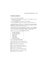
3. At the prompt, enter the Telnet command
ipAddrSet.
You are prompted for the
following:
Ethernet IP Address [current]:
Enter new Ethernet IP address (defaults
for switches 1 through 6 respectively, are 10.77.77.77, 10.77.77.76, 10.77.77.75,
10.77.77.74, 10.77.77.73, 10.77.77.72)
Ethernet Subnetmask [current]:
Enter new Ethernet subnetmask (default
is 0.0.0.0)
Fibre Channel IP Address [current]:
Enter new Fibre Channel IP
address if desired
Fibre Channel Subnet Mask [current]:
Enter new Fibre Channel
subnet mask if desired
Gateway Address [current]:
Enter new gateway address (default is
172.17.1.1)
Set IP Address now? [y = set now, n = next reboot]:
Enter “y”
to set now by restarting the switch element
4. Type
IPaddressShow
to verify that the address was set correctly.
5. Repeat steps 1 through 4 above for the remaining five switch elements in the SAN
Integrated Switch.
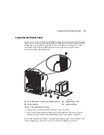
6. After you enter the values, disconnect the serial cable and store it in a secure location.
Use the dust cover supplied with the switch to protect the serial port connection during
normal operation of the switch.