background image


Chapter 

1


Introduction 

Overview 

For the latest functionality, features, and operating system support for the NC3120 Server 
Adapter, see the networking page at


compaq.com 

Hardware Overview 

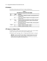
The NC3120 Server Adapter has three diagnostic LED indicators that show if there is a problem 
with the connector, cable, or hub.  

Figure 1-1.  Compaq NC3120 Server Adapter 


Summary of Contents for NC3120

Page 1: ...NC3120 Fast Ethernet Server Adapter User Guide Fourth Edition January 2003 Part Number 234554 00D Compaq Computer Corporation...

Page 2: ...and other countries All other product names mentioned herein may be trademarks of their respective companies Compaq shall not be liable for technical or editorial errors or omissions contained herein...

Page 3: ...5 Cable 1 2 Chapter 2 Installing the Adapter Electrostatic Discharge Precautions 2 1 Installing the Adapter in a Server 2 2 Connecting the Network Cable 2 3 Appendix A Regulatory Compliance Notices F...

Page 4: ...Guide Appendix C Specifications NC3120 Fast Ethernet Server Adapter Specifications C 1 UTP Cable Specifications C 2 10BASE T C 2 100BASE T C 2 RJ 45 Pinouts and Crossover Function C 2 10 100 Straight...

Page 5: ...f the procedures precautions and hazards associated with equipment containing hazardous energy circuits Symbols in Text These symbols may be found in the text of this guide They have the following mea...

Page 6: ...evel or to make modifications to any printed wiring board Improper repairs could create conditions that are hazardous WARNING To reduce the risk of electric shock or damage to the equipment If the sys...

Page 7: ...Compaq Web based support services visit http www compaq com support Navigate to a specific product and then look for support information from this list of support resources For a complete list of avai...

Page 8: ...add in cards in your server The amount of memory in your server North America The Compaq Customer Support department for North America can be reached at 1 800 652 6672 1 800 OKCOMPAQ For continuous qu...

Page 9: ...perating system support for the NC3120 Server Adapter see the networking page at compaq com Hardware Overview The NC3120 Server Adapter has three diagnostic LED indicators that show if there is a prob...

Page 10: ...e cable connection is secure ACT Off No network data is being sent or received The adapter is not receiving power or the cable connection is faulty On The adapter is sending or receiving data at 100 M...

Page 11: ...s associated with products capable of producing hazardous energy levels NOTE Before removing the cover of your server refer to the Compaq documentation for the proper methods for installing a PCI card...

Page 12: ...lug the power cord 2 Remove the server cover and the cover bracket from a PCI slot WARNING To reduce the risk of personal injury from hot surfaces allow the internal system components to cool before t...

Page 13: ...2 3 Connecting the Network Cable Network connections for the NC3120 Server Adapter can employ existing UTP Category 5 or better cable for 100 Mb s transmissions and UTP Category 3 or better cable for...

Page 14: ...the user is encouraged to try to correct the interference by one or more of the following measures Reorient or relocate the receiving antenna Increase the separation between the equipment and receiver...

Page 15: ...l apparatus meets all requirements of the Canadian Interference Causing Equipment Regulations Avis Canadien Cet appareil num rique de la classe B respecte toutes les exigences du R glement sur le mat...

Page 16: ...Regulatory Compliance Notices A 3 China Taiwan Notice Japanese Notice...

Page 17: ...c sensitive component or assembly Grounding Methods There are several methods for grounding Use one or more of the following methods when handling or installing electrostatic sensitive parts Use a wri...

Page 18: ...de only 802 3x 802 1p 802 1Q Dimensions 5 4 x 4 8 inches L x W 13 7 cm x 12 2 cm including bracket Connector and Distances One RJ 45 100 meters 328 feet Interrupts Supported Automatically configured T...

Page 19: ...iver of a device at the other end and vice versa The crossover function may be implemented internally at the hub or switch or externally through the twisted pair media 10 100 Straight Through Pinouts...

Page 20: ...twisted pair media using the physical pinouts indicated in Table C 3 Table C 3 10 100 Pinouts Using External Crossover Pin Function Color Match Function Pin 1 TD White Orange RD 3 2 TD Orange White R...

Reviews: