background image

3-2

    Service Manual

3.1


Checking Self-Test Results: Console Display

The self-test console display gives information for the TLSB modules
and the PCIs in the system.

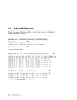
Example 3–1   System Self-Test Console Display

F   E   D   C   B   A   9   8   7   6   5   4   3   2   1   0   NODE # 

                            A   M   M   M   .   .   P   P   P   TYP    

                            o   +   +   +   .   .   ++  ++  ++  ST1    

                            .   .   .   .   .   .   EE  EE  EB  BPD    

                            o   +   +   +   .   .   ++  ++  ++  ST2    

                            .   .   .   .   .   .   EE  EE  EB  BPD    

                            o   +   +   +   .   .   ++  ++  ++  ST3    

                            .   .   .   .   .   .   EE  EE  EB  BPD    

                    +   +   +   +   +   +   +  .   .   .   . +  C0 PCI +

                            .   .   .   .   .   .   .   .          EISA +

.   .   .   .   .   .   .   .   .   .   .   .   .   .   .   .   C1 

.   .   .   .   .   .   .   .   .   .   .   .   .   .   .   .   C2
.   .   .   .   .   .   .   .   .   .   .   .   .   .   .   .   C3

                                B0  A1   A0   .   .   .  .  .  ILV 

                            .  4GB  4GB  4GB  .   .  .  .  .   12GB 

Compaq AlphaServer GS60E2-6/700/8, Console V5.5-25 26-OCT-1999 12:06:03

SROM V2.3, OpenVMS PALcode V1.68-101, Tru64 UNIX PALcode V1.61-101 

System Serial = NI84177052, OS = OpenVMS,  3:11:57  December 7, 1999

:
:

P00>>>

Summary of Contents for AlphaServer GS60E

Page 1: ...l Order Number EK GS60E SV A01 This manual is intended for Compaq service engineers It includes troubleshooting information configuration rules and instructions for removal and replacement of field replaceable units FRUs for the Compaq AlphaServer GS60E system ...

Page 2: ...Notice The equipment described in this manual generates uses and may emit radio frequency energy The equipment has been type tested and found to comply with the limits for a Class A digital device pursuant to Part 15 of FCC rules which are designed to provide reasonable protection against such radio frequency interference Operation of this equipment in a residential area may cause interference in ...

Page 3: ......

Page 4: ......

Page 5: ...l Panel 2 2 2 2 Troubleshooting TLSB Modules 2 6 2 3 Troubleshooting a PCI Shelf 2 8 2 4 Troubleshooting StorageWorks Shelves 2 10 2 5 Troubleshooting the Power Subsystem 2 12 2 6 Troubleshooting the Cooling Subsystem 2 14 Chapter 3 Console Display and Diagnostics 3 1 Checking Self Test Results Console Display 3 2 3 2 Show Configuration Display 3 4 3 3 Running Diagnostics the Test Command 3 6 3 4 ...

Page 6: ...hine Check Error Log 4 42 Chapter 5 Removal and Replacement Procedures 5 1 TLSB Modules 5 2 5 1 1 How to Replace the Only Processor 5 2 5 1 2 How to Replace the Boot Processor 5 4 5 1 3 How to Add a New Processor or Replace a Secondary Processor 5 8 5 1 4 Processor Memory or Terminator Module Removal and Replacement 5 12 5 1 5 SIMM Removal and Replacement 5 14 5 1 6 I O Cable and KFTHA Module Remo...

Page 7: ...Console Mode No Failing SIMMS 3 12 3 7 Console Mode Failing SIMMs Found 3 13 3 8 Examples of the Info Command 3 14 4 1 Producing an Error Log with DECevent 4 4 4 2 Summary Error Log 4 5 4 3 OSF Event Type Identification 4 7 4 4 OpenVMS Event Type Identification 4 7 4 5 Sample Machine Check 660 Error Log Entry 4 8 4 6 Sample Machine Check 620 Error Log Entry 4 17 4 7 Sample DWLPB Motherboad Error L...

Page 8: ...Troubleshooting Steps for PCI Shelf 2 9 2 6 Troubleshooting StorageWorks Devices and Shelves 2 10 2 7 Power Subsystem 2 12 2 8 Cooling Subsystem 2 14 2 9 Cabinet Airflow 2 15 3 1 Hose Numbering Scheme for KFTHA 3 5 4 1 Error Log Header Structure 4 31 5 1 Processor Memory or Terminator Module 5 12 5 2 Removing a SIMM 5 14 5 3 SIMM Connector Numbers E2035 Module 5 16 5 4 SIMM Connector Numbers E2036...

Page 9: ...rol Panel LEDs at Power Up 2 3 2 3 SCSI Disk Drive LEDs 2 11 4 1 TLSB Address Bus Commands 4 2 4 2 Supported Event Types 4 6 4 3 Parsing a Sample 660 Error Example 4 5 4 8 4 4 Parsing a Sample 620 Error Example 4 6 4 17 4 5 Parsing a DWLPB Motherboard Error Example 4 7 4 24 5 1 Cables 5 43 B 1 Summary of Console Commands B 1 B 2 Environment Variables B 5 B 3 Settings for the graphics_switch Enviro...

Page 10: ......

Page 11: ...stem bus modules and power subsystem Chapter 2 Troubleshooting with LEDs tells how to use the LEDs and other indicators to find problem components in the system Chapter 3 Console Display and Diagnostics tells how to use these tools to find nonfunctioning components in the system Chapter 4 DECevent Error Log describes how to interpret the error log produced by this utility program Chapter 5 Removal...

Page 12: ...E72 Installation Guide EK KFE72 IN Service Information AlphaServer GS60E Service Manual EK GS60E SV Reference Manual AlphaServer GS60E and GS140 Getting Started with Logical Partitions EK TUNLP SF Upgrade Manuals GS60 8200 to GS60E Upgrade Manual EK GS60E UP H7506 Power Supply Installation Card EK H7506 IN RRDCD Installation Card EK RRDXX IN Information on the Internet Visit the Compaq Web site at...

Page 13: ...ery large memory capacities up to eight high performance CPUs and many other features normally associated with mainframe systems This chapter introduces the AlphaServer GS60E system Sections in this chapter include System Overview TLSB System Bus Processor Module MS7CC Memory Module KFTHA Module Power Subsystem Overview I O Bus and In Cab Storage Devices Troubleshooting Overview ...

Page 14: ... family It uses the same system bus the TLSB with seven slots It provides the reliability and availability features normally associated with mainframe systems The GS60E has redundant hot swappable N 1 power supplies Figure 1 1 AlphaServer GS60E System SM11 99 2nd Expander Cabinet System Cabinet 1st Expander Cabinet ...

Page 15: ... other indicators to troubleshoot the system Chapter 3 describes the console display and diagnostics The error log produced by the DECevent utility program is described in Chapter 4 Removal and replacement procedures for FRUs are described in Chapter 5 AlphaServer GS60E Options A list of the latest supported options is on the Internet which you can access as follows Using ftp copy the file ftp ftp...

Page 16: ...mory array modules and up to three I O modules The TLSB bus interconnects the CPU memory and I O modules Figure 1 2 TLSB Card Cage OM24 99 Front Rear 4 5 6 7 8 0 1 2 3 Power Filter Centerplane First CPU Additional CPUs or Memories I O Module First Memory or Additional I O or CPU Module Additional Memory I O or CPU Modules Not used Not used ...

Page 17: ...st KFTHA module goes in slot 8 a second in slot 7 and a third in slot 6 3 Place memory modules last The first memory module goes in the highest numbered open slot the next in the lowest numbered open slot and so on alternating between highest and lowest numbered open slots 4 Fill all remaining open slots with terminator modules About the TLSB Card Cage Modules used in this system are Terminator 1 ...

Page 18: ...ce Manual 1 3 Processor Module Up to four processor modules can be used in an AlphaServer GS60E system Each processor module contains two CPU chips Figure 1 3 Processor Module SM13 99 6 2 3 4 5 1 5 Side 1 Side 2 ...

Page 19: ...d system operations The 21264 A chip has a 64 Kbyte instruction cache and a 64 Kbyte data cache Cache Memory 4 Mbyte L2 cache per CPU 21264 and 8 Mbyte ECC L2 onboard cache per CPU 21264A TCC The TurboLaser control chip TCC takes commands from both CPUs and issues them to the TLSB It also controls all data movements through the TDI and SWI chips SWIs Two swizzle SWI chips receive data from the 256...

Page 20: ... Module The GS60E uses three variants of the MS7CC memory module 1 Gbyte 2 Gbytes and 4 Gbytes Up to 20 Gbytes of memory can be configured using combinations of the three module variants Figure 1 4 MS7CC Memory Module SM14 99 1 1 2 2 3 4 ...

Page 21: ...SRs The control address interface CTL gate array that provides the interface to the TLSB controls DRAM timing and refresh runs memory self test and contains TLSB and memory specific registers The DC to DC converter All types of SIMMs for all the memory modules available for AlphaServer GS60E systems are field replaceable Section 3 6 describes how to isolate a problem SIMM When you replace a SIMM y...

Page 22: ...1 10 Service Manual 1 5 KFTHA Module The KFTHA module offers four hose connections that interface between the TLSB and the I O subsystem Figure 1 5 KFTHA Module Hoses Hoses OM32 99 ...

Page 23: ...ng 32 bits from two hoses I O cables connecting to an adapter in an associated I O bus Data on the HDPs flow in one direction either up to the KFTHA or down to the I O adapter Four I O data path IDP chips which together handle a 256 bit data transfer to or from the TLSB system bus An I O control chip ICC houses the primary control logic for the TLSB interface A DC to DC converter that converts the...

Page 24: ...tem consists of an AC input box a DC distribution module redundant hot swap power supplies a cabinet control logic CCL panel and cables Figure 1 7 GS60E Power Subsystem Power Supplies Power Supplies DC Distribution Module AC Input Box CCL Panel GS60E23 99 Front Rear ...

Page 25: ...stem by cable through the AC input box see Figure 1 7 The H7506 power supplies convert three phase AC power to 48 VDC Three hot swappable power supplies offer n 1 redundancy that is if any one power supply fails the remaining two supply the needed power ...

Page 26: ...esigned to hold PCI shelves and StorageWorks I O shelves Figure 1 8 I O Bus and In Cab Storage Front View CD Drive and optional floppy drive Blowers DWLPB PCI Power Supplies AC Input Box StorageWorks Shelf 7 Slot System Bus Up to 4 CPU Modules 8 CPUs Up to 5 Memory Modules 12 GB Up to 3 I O Modules Rear View CCL Panel SM18 99 ...

Page 27: ...even devices including a signal converter and 3 25 inch disks or tapes A power unit DC to DC converter is in the leftmost slot of shelf The system cabinet has space for up to two PCI shelves DWLPB DA and three StorageWorks shelves BA36R RC RD UltraSCSI Each expander cabinet has space for four PCI shelves and three StorageWorks shelves or three PCI shelves and four StorageWorks shelves ...

Page 28: ...test display see Section 3 1 Check power subsystem see Section 2 5 No Yes No Yes SM19 99 No Type init command Check system self test display see Section 3 1 Identify faulty FRU Power down system and Boot operating system check error log see Chapter 4 replace FRU Power up You cannot find cause of user problem by phone Go to site and follow these steps If system self test passes boot operating syste...

Page 29: ...ting tools as shown in Figure 1 10 Chapters 2 3 and 4 tell how to use these tools to isolate faulty components or report software problems for AlphaServer GS60E systems Figure 1 10 Troubleshooting Tools SM110 99 Error Log Printout System Self Test and Other Console Displays LEDs and Indicators Tools for Finding Problems ...

Page 30: ......

Page 31: ...ystem bus TLSB modules processor memory and I O the I O bus and devices in shelves The cooling subsystem consists of two blowers located in the center of the system cabinet They can be checked by looking and listening for the fans Sections in this chapter are as follows Operator Control Panel Troubleshooting TLSB Modules Troubleshooting a PCI Shelf Troubleshooting StorageWorks Shelves Troubleshoot...

Page 32: ...1 Operator Control Panel LEDs Light Color State Meaning Run Green On Power is supplied to entire system the blowers are running System has exited console Power Green On System is powered on Fault Yellow On Fault on system bus On Green On Power is supplied to the whole system Secure Green On Indicates input from the console device is prevented Reset Yellow On Indicates a system reset has occurred c...

Page 33: ... will also blink but do not provide power supply status Table 2 2 Operator Control Panel LEDs at Power Up Action Keyswitch On On Off Button On Run Power Fault On Secure Reset Set circuit breaker to On Off Blink Blink Blink Blink Blink Blink Turn keyswitch to On and press On button On Off On Blink On Off Off System self test starts On Off On On On Off Off Module passes self test On Off On Off On Of...

Page 34: ...raphics terminal connected through a PCI bus Connect a character cell terminal through the serial port on the system cabinet Repeat A SM22 99 If a faulty component or firmware update was identified as the problem replace the component or update the firmware If the problem has not yet been identified go to 1 2 2 2 2 2 Fault LED is lit Some component failed system self test If Run and On are green F...

Page 35: ...ights on control panel replace control panel Proceed with Any LEDs lit on control panel Status LEDs are not receiving power signals No Yes Green LED s lit System self test passed On is lit Yes operating system running Run is lit If both green LEDs are lit system self test has passed and the operating system is running Check the error log see Chapter 4 Ensure that the proper boot disk is selected t...

Page 36: ... 6 Service Manual 2 2 Troubleshooting TLSB Modules You can check individual module self test results by looking at the status LEDs on the module Figure 2 3 TLSB Module LEDs CPU Memory KFTHA SM24 99 LEDs ...

Page 37: ... Failure of the built in self test for the MS7CC modules indicates that testing has shown that there is no single 64 Kbyte segment of memory that is usable Each 64 Kbyte segment must show at least 256 bad pages before it is noted as unusable However it is possible for a SIMM to warrant replacement even though the module as a whole passes its self test You can determine faulty SIMMs with the show c...

Page 38: ...s of the power supplies as well as the adapter self test results in the PCI shelf Figure 2 4 PCI Shelf 1 2 3 4 DWLPB LED numbers OM55 99 LED Status in PCI Shelf LED 1 On board power system OK LED 2 Motherboard self test passed LED 3 48 VDC power supply OK LED 4 Hose Error ...

Page 39: ... Power Supply 1 Yes OM56 99 1 2 2 LED 1 lit No Internal Power System Error Check fans in blower check for jumper cable a small plug replacing fan connection Replace Power Board 13 4 Yes No Replace Motherboard 1 5 LED 2 lit Yes LED 4 lit Yes Hose Error 1 6 Some error has occurred in the protocol governing the transfer of data over the hose Replace the hose first the mother board second the KFTHA th...

Page 40: ...StorageWorks Shelves StorageWorks devices are mounted in horizontal shelves in the GS60E system or expander cabinet LEDs are located on each disk drive Figure 2 6 Troubleshooting StorageWorks Devices and Shelves OM57 99 Yellow LEDs Green LEDs ...

Page 41: ...Troubleshooting with LEDs 2 11 Table 2 3 SCSI Disk Drive LEDs Indicator LED LED State Meaning Green Off Flashing On No activity Activity Activity Yellow Off Flashing On Normal Spin up spin down Not used ...

Page 42: ...60E power supplies accept three phase AC and produce 48 VDC power Each power supply has two LEDs that indicate normal conditions and faults Figure 2 7 Power Subsystem Front VAUX LED top 48V LED bottom SM27 99 Power Supplies Rear AC Power Line Cord Main Circuit Breaker ...

Page 43: ...ircuit breaker CB1 controls power to the entire system including the power supplies blowers and in cabinet options Current overload causes the breaker to trip to the Off position so that power to the system is turned off For normal operation circuit breaker CB1 must be in the On position with the handle pushed up To shut the circuit breaker off push the handle down Sub breakers CB2 through CB11 sh...

Page 44: ...shooting the Cooling Subsystem The cooling system cools the power subsystem the TLSB card cage and shelves Figure 2 8 Cooling Subsystem Front View SM28 99 CD Drive Blowers DWLPB PCI Power Supplies AC Input Box StorageWorks Shelf TLSB ...

Page 45: ...s in the front and 1 meter in the rear to maximize airflow Two blowers located in the center of the cabinet see Figure 2 8 draw air downward through the TLSB card cage Air is exhausted at the middle of the cabinet to the rear see Figure 2 9 The blower speed varies based on the system s ambient temperature CAUTION Anything placed on the top of the cabinet could restrict airflow This will cause the ...

Page 46: ......

Page 47: ...w hardware diagnostic programs are executed when the system is initialized Sections include Checking Self Test Results Console Display Show Configuration Display Running Diagnostics the Test Command Testing the Entire System Sample Test Command for a Memory Module Identifying a Failing SIMM Info Command ...

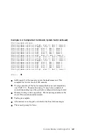
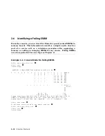
Page 48: ...f Test Console Display F E D C B A 9 8 7 6 5 4 3 2 1 0 NODE A M M M P P P TYP o ST1 EE EE EB BPD o ST2 EE EE EB BPD o ST3 EE EE EB BPD C0 PCI EISA C1 C2 C3 B0 A1 A0 ILV 4GB 4GB 4GB 12GB Compaq AlphaServer GS60E2 6 700 8 Console V5 5 25 26 OCT 1999 12 06 03 SROM V2 3 OpenVMS PALcode V1 68 101 Tru64 UNIX PALcode V1 61 101 System Serial NI84177052 OS OpenVMS 3 11 57 December 7 1999 P00 ...

Page 49: ... processor from the possibility of becoming the boot processor This BPD line is printed three times After the first determination of the boot processor the processors go through two more rounds of testing Since it is possible for a processor to pass self test at line ST1 and fail ST2 or ST3 testing the processors again determine the boot processor following each round of tests The first processor ...

Page 50: ...a0 8 KFTHA 2000 0000 kftha1 C0 PCI connected to kftha0 pci0 0 SIO 4828086 0003 sio0 7 KZPSA 8101 0000 kzpsa0 8 ISP1020 8101 0000 kzpsa1 A DAC960 11069 0000 dac0 Controllers on SIO sio0 0 DECchip 21040 AA 21011 0000 tulip0 1 FLOPPY 2 0000 floppy0 2 KBD 3 0000 kbd0 3 MOUSE 4 0000 mouse0 P00 The first grouping shows the modules on the TLSB bus and their status In this example the processor is in slot...

Page 51: ...DA960 controller These lines show the controllers on the SIO module Figure 3 1 shows the connector numbering scheme for the KFTHA module Each slot has four connector numbers associated with it numbered in increasing order from top to bottom as shown Figure 3 1 Hose Numbering Scheme for KFTHA 8 C0 TLSB node 7 6 5 4 C3 C4 Centerplane SM31 99 C7 C8 C11 ...

Page 52: ...ingle module a group of devices or a single device Example 3 3 Sample Test Commands P00 test Tests the entire system Default run time is 10 minutes P00 t pci0 t 60 Tests all devices associated with the PCI0 subsystem Test run time is 60 seconds P00 test ms Tests all ms7cc memory modules P00 t q Status messages will not be displayed during test time ...

Page 53: ...ROM on the boot processor module No module self tests are executed when the test command is issued without a mnemonic When you specify a subsystem mnemonic or a device mnemonic with test such as test pci0 or test ms7cc0 self tests are executed on the associated modules first and then the appropriate exercisers are run ...

Page 54: ...n internal loopback mode Starting device exerciser on dka0 0 0 4 0 id 36f in READ ONLY mode Stopping device exerciser on dka0 0 0 4 0 id 36f Starting device exerciser on dka100 1 0 4 0 id 5df in READ ONLY mode Stopping device exerciser on dka100 1 0 4 0 id 5df Starting device exerciser on dka200 2 0 4 0 id 858 in READ ONLY mode Stopping device exerciser on dka200 2 0 4 0 id 858 Starting device exe...

Page 55: ...nits on floppy0 slot 0 bus 1 hose 0 Shutting down units on isp0 slot 4 bus 0 hose 0 Shutting down units on isp1 slot 6 bus 0 hose 0 Shutting down units on isp2 slot 7 bus 0 hose 0 Shutting down units on isp3 slot 8 bus 0 hose 0 Shutting down units on tulip1 slot 11 bus 0 hose 0 P00 In Example 3 4 the operator enters the test command The complete test suite runs for 1200 seconds To stop execution o...

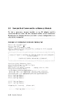
Page 56: ...onds Type Ctrl C to abort ALLOW AT LEAST 2 MINUTES OF TESTING TIME FOR EACH GIGABYTE OF MAIN MEMORY SINGLE BIT ERROR REPORTING IS ENABLED Starting Cache Coherency Tests Starting Marching 1 s and 0 s Tests Memory size is 8192 MB More than 2 GB memory present memory size is 1FFE Starting Victimize Tests 2 GB memory testing beginning Starting test 4 at addresses 7F400000 and 10F800000 Starting test 2...

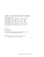
Page 57: ... 0 hose 4 Shutting down units on isp7 slot 9 bus 0 hose 4 Shutting down units on isp8 slot 10 bus 0 hose 4 Shutting down units on tulip3 slot 11 bus 0 hose 4 Shutting down units on tulip0 slot 12 bus 0 hose 0 Shutting down units on floppy0 slot 0 bus 1 hose 0 Shutting down units on isp0 slot 4 bus 0 hose 0 P00 In Example 3 5 Enter test ms All MS7CC memory modules are tested by the memory exerciser...

Page 58: ...ole Mode No Failing SIMMS P00 set simm_callout on P00 init Initializing WARNING SIMM_CALLOUT environment variable is ON F E D C B A 9 8 7 6 5 4 3 2 1 0 NODE A M M M P P P TYP o ST1 EE EE EB BPD o ST2 EE EE EB BPD o ST3 EE EE EB BPD C0 PCI EISA C1 C2 C3 B0 A1 A0 ILV 4GB 4GB 4GB 12GB Compaq AlphaServer GS60E2 6 700 8 Console V5 5 25 26 OCT 1999 12 06 03 SROM V2 3 OpenVMS PALcode V1 68 101 Tru64 UNIX...

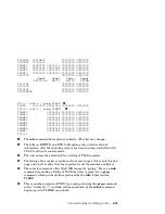
Page 59: ...MMS In Example 3 6 no faulty SIMMs were found The set simm callout off command turns off the environment variable that enabled callout of faulty SIMMs The init command initializes the system in normal mode Example 3 7 shows a show simm command that calls out some failing SIMMs Section 5 1 5 tells how to locate remove and replace SIMMs in a memory module Example 3 7 Console Mode Failing SIMMS Found...

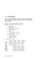
Page 60: ... 11 Page Tables 12 FRU table 13 Console internals 14 Supported devices 15 Console SCB 16 PCIA Enter selection 5 Node0 Node1 Node 7 Node8 KN7CG AB MS7CC MS7CC KFTHA Base adr 88000000 88800000 89c00000 8a000000 TLDEV 00005000 00008014 00002020 00002000 TLBER 00100000 00800000 00000000 00000000 TLCNR 000fc200 00000220 00000170 00000180 TLVID 00000080 00000054 TLMMR0 00008014 80000010 80000010 TLMMR1 ...

Page 61: ...MR5 00008014 00000000 00000000 TLMMR6 00008014 00000000 00000000 TLMMR7 00008014 00000000 00000000 P00 The info command lists options available This list may change The bitmap HWRPB and FRU table options only provide relevant information after the operating system has been running and halted with Ctrl P to return to console mode The user enters the selection 5 for a listing of TLSB registers The l...

Page 62: ......

Page 63: ...apter discusses error logs produced by the DECevent bit to text translator Sections include Brief Description of the TLSB Bus Producing an Error Log with DECevent Getting a Summary Error Log Supported Event Types Sample Error Log Entries Console Halt Conditions ...

Page 64: ...t initiates a transaction is called a commander node The node that responds to the command issued by the commander is called the slave node CPUs or I O nodes are always the commander on memory transactions and can be either the commander or the slave on CSR control and status register transactions Memory nodes are never commander nodes 4 1 1 Command Address Bus Table 4 1 lists the eight address bu...

Page 65: ... whenever TLSB_SHARED or TLSB_DIRTY are asserted to ensure that should an error occur in transmission or reception of either one of these signals it can be detected For example if TLSB_SHARED or TLSB_DIRTY is asserted but TLSB_STACHK is not there is an error Or if TLSB_STACHK is asserted and TLSB_SHARED or TLSB_DIRTY is not there is also an error 4 1 3 Error Checking The TLSB is designed to implem...

Page 66: ... intermittent errors These errors may or may not cause the operating system to crash Example 4 1 Producing an Error Log with DECevent diagnose output errlog dat DECevent Version V3 0 In this example the error log information is directed to a file called errlog dat If the output qualifier is not used the error log information is displayed on the screen of the console terminal ...

Page 67: ...lyzing the error log It gives you a table of contents for the error log Example 4 2 Summary Error Log diagnose summary SUMMARY OF ALL ENTRIES LOGGED ON NODE CLYP01 Unknown major class New errorlog created 1 Timestamp 3 Machine check 670 entry 7 Crash Re start 2 System startup 3 Volume mount 3 Adapter Error 4 Soft ECC error 1 ...

Page 68: ...e check 660 660 system machine checks 630 error interrupts 630 correctable processors checks 620 errors 620 correctable system errors Extended CRD Memory single bit error footprints Adapter Adapter is logging entity Adapters include the KFTHA module and the DWLPB motherboard Example 4 3 and Example 4 4 show a Tru64 UNIX entry for a 670 type machine check and an OpenVMS 620 error entry for a CRD co...

Page 69: ...0000006 Event validity 1 Valid Entry type 100 CPU Machine Check Errors CPU Minor class 1 Machine check 670 entry Event severity 1 Severe Priority Example 4 4 OpenVMS Event Type Identification ENTRY 124 Logging OS 1 OpenVMS System Architecture 2 ALPHA OS version V7 2 1 Event sequence number 102 Timestamp of occurrence 2 NOV 1999 17 45 05 Host name CLYP01 AXP HW model AlphaServer GS60E Number of CPU...

Page 70: ...ster DOUBLE BIT FILL ERR is set The TLBER register is next in the parse tree UNCORRECTABLE DATA ERROR is set The TLBER register on the memory module is set to an UNCORRECTABLE DATA ERROR indicating that the source of the 660 is a memory module Example 4 5 Sample Machine Check 660 Error Log Entry ENTRY 1 Logging OS 2 Digital UNIX System Architecture 2 Alpha Event sequence number 8 Timestamp of occu...

Page 71: ...320C80 DC1_SYNDROME x0000000000000000 DC0_SYNDROME x00000000000000D4 C_STAT x0000000000000010 Bits 04 00 Bx10000 DOUBLE BIT FILL ERR C_STS x0000000000000002 Bits 03 00 Bx0010 INIT mode Dirty MM_STAT x0000000000000280 OPCODE x0000000000000028 Dcache Parity OK EXC_ADDR xFFFFFFFFB44CCB50 NO Bits Set Addr Field_1 Bits 31 02 x000000002D1332D4 Addr Field_2 Bits 63 32 x00000000FFFFFFFF IER_CM x0000007EE0...

Page 72: ...ernel Mode VA_48 43 Bit Virtual Address used VA_FORM_32 Bit NOT Set Single_Issue_L Bottom Up Performance Counter 0 Disabled Performance Counter 1 Disabled CALL_PAL link Reg is R23 MCHK Check Enabled Processor ID EV6 Pass 2 3 VPTB Bits 47 30 x000000000003FFF0 VPTB Bits 63 48 x000000000000FFFF PCTX x0000628000000004 Floating Point Enb ASTER 00 Kernel ASTRR 00 Kernel System Registers WHAMI x0000 TLSB...

Page 73: ...TRY_Count 2 10 retries 6 0us on idle system min DISABLE PROBE Number 0 tbc fast path disabled dm_dslb_prio fills probes victims or wrio en_fst_vq en_fst_prq en_fts_writes TCCERR x00011800 TCC Chip Revision x00000001 TDIERR x00000000 INTR MASK 0 x000001FF duart0 interrupt enable ipl 14 interrupt enable ipl 15 interrupt enable ipl 16 interrupt enable ipl 17 interrupt enable ip enable intim enable CP...

Page 74: ...V x80008025 Device Type Dual EV6 Proc 525Mhz 4meg Bcache TLBER x00110000 UNCORRECTABLE DATA ERROR Data Syndrome 0 TLCNR x00000200 TLVID x00000010 TLESR0 x0008D4D4 SYND0 x000000D4 SYND1 x000000D4 UNCORRECTABLE ECC ERROR TLESR1 x00000300 SYND0 x00000000 SYND1 x00000003 TLESR2 x00000300 SYND0 x00000000 SYND1 x00000003 TLESR3 x00000300 SYND0 x00000000 SYND1 x00000003 MODCONFIG0 x00700B80 DPQ MAX Entri...

Page 75: ... TLEP Interrupt Sum 0 x00000000 TLEP Interrupt Sum 1 x00000000 TLEP VMG x00000000 TLEPWERR0 x00000000 TLEPWERR1 x00000000 TLEPWERR2 x00000000 TLEPWERR3 x00047810 TLaser Memory Regs TLSB Node Number 4 TLDEV x00005000 Device Type Memory Module Revision x00000000 TLBER x00800000 TLCNR x000FC240 TLVID x00000080 FADR 0 x0002000000300010 FADR 1 x00020000 TLESR0 x00000300 TLESR1 x00000300 TLESR2 x0000030...

Page 76: ...2 FADR x072200004DC32000 FADR 1 x07220000 Failing Command Read Failing Bank Bank 2 TLESR0 x0009D4D4 ECC Syndrome 0 x000000D4 ECC Syndrome 1 x000000D4 TRANSMITTER DURING ERROR UNCORRECTABLE ECC ERROR TLESR1 x00000300 TLESR2 x00000300 TLESR3 x00000300 TMIR x80000002 Interleave x00000002 TMCR x00000208 256MB Module E2035 CA 4 MB DRAM 60ns DRAM Strings Installed 4 DRAM timing Bus Spd 10 0 11 2 Refresh...

Page 77: ... Installed 4 DRAM timing Bus Spd 10 0 11 2 Refresh Cnt 1360 TMER x00000000 Failing String x00000000 TMDRA x00000000 Refresh Rate 1X TDDR0 x0000000 TDDR1 x00000000 TDDR2 x00000000 TDDR3 x00000000 TLaser Memory Regs TLSB Node Number 7 TLDEV x02045000 Device Type Memory Module Revision x00000204 TLBER x00800000 TLCNR x000FC270 TLVID x00000091 FADR 0 x0012000000300010 FADR 1 x00120000 TLESR0 x00000300...

Page 78: ...0 FADR 1 x00000000 TLESR0 x00000000 TLESR1 x00000000 TLESR2 x00000000 TLESR3 x00000000 CPU Interrupt Mask x00000001 Cpu Interrupt Mask x00000001 ICCMSR x00000000 Arbitration Control Minimum Latency Mode Suppress Control Suppress after 16 Translations ICCNSE x80000000 Interrupt Enable on NSES Set ICCMTR x00000000 IDPNSE 0 x00000000 IDPNSE 1 x00000006 Hose Power OK Hose Cable OK IDPNSE 2 x00000000 I...

Page 79: ...er The next branch on the parse tree is C_STAT DSTREAM_MEM_ERR is set The TLBER register is next in the parse tree CORRECTABLE READ DATA ERROR is set The TLBER register on the memory module is next in the parse tree CORRECTABLE READ DATA ERROR is set The error log identifies the SIMM where the error occurred as J22 UNIX lists each occurrence of a corrected read data error Before replacing the SIMM...

Page 80: ...x00000001 MCHK Frame Rev 1 0 CPU Registers I_STAT x0000000800000000 Bits 31 29 Bx000 NO Error Detected DC_STAT x0000000000000008 Bits 04 00 Bx01000 DCACHE DATA CORRECTABLE ECC ERROR LOAD C_ADDRESS x0000000000874000 Address of last reported x0000000000021D00 DC1_SYNDROME x0000000000000000 DC0_SYNDROME x00000000000000D5 C_STAT x0000000000000003 Bits 04 00 Bx00011 DSTREAM_MEM_ERR C_STS x0000000000000...

Page 81: ...00003 TLESR3 x00000300 SYND0 x00000000 SYND1 x00000003 Palcode Revision x0000001300000504 Palcode Rev 5 4 19 TLSB Base Adr x0000000000000000 TLaser CPU Registers TLSB Node Number 0 TLDEV x80008025 Device Type Dual EV6 Proc 525Mhz 4meg Bcache TLBER x00800000 Data Syndrome 3 TLCNR x00000200 TLVID x00000010 TLESR0 x00000300 SYND0 x00000000 SYND1 x00000003 TLESR1 x00000300 SYND0 x00000000 SYND1 x00000...

Page 82: ...terrupt enable ipl 16 interrupt enable ipl 17 interrupt enable ip enable intim enable CPU halt enable INTRMASK1 x00000000 TLEP Interrupt Sum 0 x00000000 TLEP Interrupt Sum 1 x00000000 TLEP VMG x00000000 TLEPWERR0 x00000000 TLEPWERR1 x00000000 TLEPWERR2 x00000000 TLEPWERR3 x00041FF7 TLaser CPU Registers TLSB Node Number 1 TLDEV xB0008027 Device Type Dual EV67 Proc 700Mhz 4meg Bcache TLBER x00140000...

Page 83: ...tbc fast path disabled dm_dslb_prio fills probes victims or wrio en_fst_vq en_fst_prq en_fts_writes TCCERR x00011800 TCC Chip Revision x00000001 TDIERR x00000000 INTRMASK0 x000000FE ipl 14 interrupt enable ipl 15 interrupt enable ipl 16 interrupt enable ipl 17 interrupt enable ip enable intim enable CPU halt enable INTRMASK1 x00000000 TLEP Interrupt Sum 0 x00000000 TLEP Interrupt Sum 1 x00000000 T...

Page 84: ...J22 Second ECC Code xD5 Failing SIMM Number J22 TLESR1 x00000300 TLESR2 x00000300 TLESR3 x00000300 TMIR x80000001 Interleave x00000001 TMCR x0000020D 2GB Module E2036 AA 16 MB DRAM 60ns DRAM Strings Installed 8 DRAM timing Bus Spd 10 0 11 2 Refresh Cnt 1360 TMER x00000000 Failing String x00000000 TMDRA x00000000 Refresh Rate 1X TDDR0 x00000000 TDDR1 x00000000 TDDR2 x00000000 TDDR3 x00000000 TLaser...

Page 85: ...Control Suppress after 16 Translations ICCNSE x80000000 Interrupt Enable on NSES Set ICCMTR x00000002 Mbox Trans in Prog Hose 1 IDPNSE 0 x00000006 Hose Power OK Hose Cable OK IDPNSE 1 x00000006 Hose Power OK Hose Cable OK IDPNSE 2 x00000000 IDPNSE 3 x00000000 IDPVR x00000800 ICCWTR x00000000 TLMBPR x0000000000000000 IDPDR0 x20000000 IDPDR1 x00000000 IDPDR2 x00000000 IDPDR3 x00000000 ...

Page 86: ...ter No bits are set in this register so we follow the tree down The ERR1 register is also all zeros so we follow the tree down The ERR2 register s last digit is 9 indicating that bit 0 is set and bit 3 is set The FRUs identified for this branch of the parse tree are the KFTHA high probability PCIA DWLPB motherboard medium probability and hose I O cable connecting KFTHA to DWLPB motherboard low pro...

Page 87: ...ut Through Threshhold x00000000 IO Space HW Addr Ext x00000000 Mem Read Mult Pre fetch S 4 Cache Blocks I O Port Up Hose Buffers 3 Buffers TIOP and IOP Scatter Gather MAP RAM Si 128KB 32K entries default PCI Arbitration Control Round Robin for all Masters PCI Cut Through Enable Memory Read Multiple Enable MRETRY 0 x00400000 ERR 0 x00000000 FADR0 x00000000 DMA Read from Memory IMask PCI Interrupt 0...

Page 88: ...C10 Interrupt Vector x00000C10 Dev Vec 0 Slot 2 IntD x00000C20 Interrupt Vector x00000C20 Dev Vec 0 Slot 3 IntA x00000C30 Interrupt Vector x00000C30 Dev Vec 0 Slot 3 IntB x00000C40 Interrupt Vector x00000C40 Dev Vec 0 Slot 3 IntC x00000C50 Interrupt Vector x00000C50 Dev Vec 0 Slot 3 IntD x00000C60 Interrupt Vector x00000C60 CTL 1 x01E00100 Config Cycle Type PCI Type 0 Configuration Memory Block Si...

Page 89: ... 2 IntA x00000CF0 Interrupt Vector x00000CF0 Dev Vec 1 Slot 2 IntB x00000D00 Interrupt Vector x00000D00 Dev Vec 1 Slot 2 IntC x00000D10 Interrupt Vector x00000D10 Dev Vec 1 Slot 2 IntD x00000D20 Interrupt Vector x00000D20 Dev Vec 1 Slot 3 IntA x00000D30 Interrupt Vector x00000D30 Dev Vec 1 Slot 3 IntB x00000D40 Interrupt Vector x00000D40 Dev Vec 1 Slot 3 IntC x00000D50 Interrupt Vector x00000D50 D...

Page 90: ... Vector x00000DA0 Dev Vec 2 Slot 1 IntA x00000DB0 Interrupt Vector x00000DB0 Dev Vec 2 Slot 1 IntB x00000DC0 Interrupt Vector x00000DC0 Dev Vec 2 Slot 1 IntC x00000DD0 Interrupt Vector x00000DD0 Dev Vec 2 Slot 1 IntD x00000DE0 Interrupt Vector x00000DE0 Dev Vec 2 Slot 2 IntA x00000DF0 Interrupt Vector x00000DF0 Dev Vec 2 Slot 2 IntB x00000E00 Interrupt Vector x00000E00 Dev Vec 2 Slot 2 IntC x00000...

Page 91: ...se Address Register 3 x00000000 Base Address Register 4 x00000000 Base Address Register 5 x00000000 Base Address Register 6 x00000000 Expansion Rom Base Address x00000000 Interrupt P1 xE5 Interrupt P2 x01 Min Gnt x00 Max Lat x00 ...

Page 92: ...n Progress bit to signal exiting the handler 2 While PALcode is executing the machine tries to enter a Machine Check thus causing a Double Error halt Under both of these conditions continuing system operation is not possible and the machine state cannot be saved under normal mechanism such as error logging For these conditions PAL and the console save the appropriate state information in EEPROM Wh...

Page 93: ...boLaser 5 Product Fault Management Specification The 670 660 logout frame is the standard 288 byte packet used in error logging The TLEP sub packet is minimized so only error information is captured during the CPU DBL HALT The Byte Count is calculated on a fully populated configuration and includes one incidences of errors 1 Figure 4 1 Error Log Header Structure Revision 1 Type 11 Class 5 BC 1056 ...

Page 94: ...0 Logout 72 LW Node 0 TLEP SUB Packet mini 14 LW Node Node 8 126 LW 9Nodes PCI 0 3 LW Node PCI 19 60 LW 20PCI Total Byte Count for two events 2112 byte count TLEP Sub Packet minimized TLBER TLDEV TLESR1 TLESRO TLESR3 TLESR2 TDIERR TCCERR TLEPWERR1 TLEPWERR0 TLEPWERR3 TLEPWERR2 RESERVED RESERVED PCI Sub Packet PCIA ERR1 PCIA ERR0 PCIA ERR2 ...

Page 95: ...CCNSE IDPNSE1 IDPNSEO IDPNSE3 IDPNSE2 RESERVED RESERVED Example 4 8 CPU Double Error Halt ENTRY 1 Logging OS 1 OpenVMS System Architecture 2 Alpha OS version V6 2 Event sequence number 11 Timestamp of occurrence 31 MAY 1996 14 37 49 Time since reboot 0 Day s 0 23 53 Host name FFFA0026 System Model COMPAQ AlphaServer GS140 67 700 Entry Type 113 CPU Double Error Halt TLaser DE Halt Halt Code x000000...

Page 96: ...00100 Bits 04 00 Bx00000 NO Error C_STS x0000000000000000 Bits 03 00 Bx0000 NO Error MM_STAT x0000000000000000 OPCODE x0000000000000000 Dcache Parity OK EXC_ADDR x0000000000098000 NO Bits Set Addr Field_1 Bits 31 02 x0000000000026000 Addr Field_2 Bits 63 32 x0000000000000000 IER_CM x0000000000000000 NO Bits Set Current Mode 00 Kernel AST Interrupt Enabled x0000000000000000 Software Interrupts Enb ...

Page 97: ...based on state of chooser Branches chosen PALRES Inst NOT executed in Kernel Mode VA_48 43 Bit Virtual Address used VA_FORM_32 Bit NOT Set Single_Issue_L Bottom Up Performance Counter 0 Disabled Performance Counter 1 Disabled CALL_PAL link Reg is R27 MCHK Check Disabled Processor ID NOT Recognized VPTB Bits 47 30 x0000000000000000 VPTB Bits 63 48 x0000000000000000 PCTX x0000000000000000 ASTER 00 K...

Page 98: ...he size 4MB TLMODCONFIG1 x00098AD4 P0 Reqest ID line 2 P1 Reqest ID line 5 TLMBPR_RETRY_Count 2 8 retries 1 5us on idle system min fault disabled on TLSB P0 req disabled DISABLE PROBE Number 0 tbc fast path enabled dm_dslb_prio probes fills victims or wrio wspc_error_en TCCERR x00004000 TCC Chip Revision x00000000 TDIERR x00000000 INTR MASK 0 x000001FF duart0 interrupt enable ipl 14 interrupt enab...

Page 99: ...it 1 Address Valid TLSB Node 5 Node 5 TLDEV x00005000 Device Type Memory Module Revision x00000000 TLBER x00100000 TLESR0 x00000303 TLESR1 x00000C0C TLESR2 x00006060 TLESR3 x00009090 TLFADR1 TLFADR0 x008500000011E940 TLVID x00000080 TLMIR x80000001 Interleave x00000001 MCR x00000235 512MB Module E2035 DA 16 MB DRAM 60ns DRAM Strings Installed 2 DRAM timing Bus Spd 13 0 15 0 Refresh Cnt 1008 MER x0...

Page 100: ...Device Type I O Module TLBER x00000000 TLESR0 x00000000 TLESR1 x00000000 TLESR2 x00000000 TLESR3 x00000000 ICCNSE x80000000 Interrupt Enable on NSES Set ICCWTR x00000008 Window Space Trans in Prog Hose 3 IDPNSE 0 x00000000 IDPNSE 1 x00000000 IDPNSE 2 x00000000 IDPNSE 3 x00000007 HOSE ERROR SIGNAL ASSERTED Hose Power OK Hose Cable OK IOP PCI 4 IOP Node 7 Hose 0 PCIERR 0 x00000000 PCIERR 1 x00000000...

Page 101: ...ame One frame is built for both processor and system detected errors Machine check logout 670 contain EV6 CPU specific error registers while machine check logout 660 contains system specific error registers 63 48 47 32 31 16 15 00 Common Area R S D C Frame Size 00 System Area Offset CPU Area Offset 08 MCHK Frame Rev MCHK CODE 10 CPU Area ISTAT 18 DC_STAT 20 C_ADDR 28 DCI_SYNDROME 30 DCO_SYNDROME 3...

Page 102: ...D TLCNR B0 TLESR1 TLESR0 B8 TLESR3 TLESR2 C0 TLMODCONFIG1 TLMODCONFIG0 C8 TDIERR TCCERR D0 TLINTRMASK1 TLINTRMASK0 D8 TLINTRSUM1 TLINTRSUM0 E0 TLEPWERR0 TLEP_VMG E8 TLEPWERR2 TLEPWERR1 F0 RESERVED TLEPWERR3 F8 RESERVED RESERVED 100 RESERVED RESERVED 108 RESERVED RESERVED 110 RESERVED RESERVED 118 ...

Page 103: ...detected errors that are correctable Machine check logout 630 contains EV6 CPU specific errors registers while machine check logout 620 contains system specific error registers 63 48 47 32 31 16 15 00 Common Area R S D C Frame Size 00 System Area Offset CPU Area Offset 08 MCHK Frame Rev 8 MCHK CODE 10 CPU Area ISTAT 18 DC_STAT 20 C_ADDR 28 DCI_SYNDROME 30 DCO_SYNDROME 38 C_STAT 40 C_STS 48 MM_STAT...

Page 104: ... TL6 Error Log Size The Operating System Header for OpenVMS and Compaq Tru64 UNIX remains the size as the TL5 The Software Error Flags Common TLEP Header Area and PALcode revision area are also unchanged in size The TLEP Machine Check Frames for 670 660 and 630 620 have different sizes relative to the TL5 63 48 47 32 31 16 15 00 Operating System Errorlog Header VMS 96b OSF 56b Software Error Flags...

Page 105: ...e Register Name Signal Name Register Bit Position TLBER DTO DE SEQE DCTCE ABTCE UACKE FDTCE CWDE2 CRDE CWDE UDE REQDE FNAE MMRE ACKTCE RTCE NAE BBE APE ATCE TLBER 31 25 19 16 9 4 2 0 TCCERR P1_ILLEGAL_CMD P0_ILLEGAL_CMD CSR_XACTION_ERR CSR_WR_NXM P1_FATAL_MMRE P0_FATAL_MMRE FAULT_ASSERTED WSPC_RD_ERROR SYSFAULT SYSDERR P1_TLMBPR_T0 P0_TLMBPR_T0 TCCERR 21 20 14 13 10 4 1 0 TDIERR P1T0 P0T0 TDIERR 1...

Page 106: ...lid Bits 08 TLBER TLDEV 10 TLVID TLCNR 18 TLESR1 TLESR0 20 TLESR3 TLESR2 28 TLMODCONFIG1 TLMODCONFIG0 30 TDIERR TCCERR 38 TLINTRMASK1 TLINTRMASK0 40 TLINTRSUM1 TLINTRSUM0 48 TLEPWERR0 TLEP_VMG 50 TLEPWERR2 TLEPWERR1 58 RESERVED TLEPWERR3 60 RESERVED RESERVED 68 RESERVED RESERVED 70 RESERVED RESERVED 78 TLDEV TurboLaser Device Register BB 0000 The device register contains information to identify a ...

Page 107: ...CHIP SPEED EV5 EV56 27 24 M 0 350MHZ 0 300MHZ 1 525MHZ 2 437MHZ 3 625MHZ with 8M BCACHE 5 625MHZ with 4M BCACHE 6 CHIP SPEED EV6 27 24 M 0 525MHZ 0 700MHZ 1 DTYPE 15 0 M 0 I O MODULE 2000 INTERGRATED I O MODULE 2020 MEMORY MODULE 5000 SINGLE PROCESSOR 4M BCACHE 8011 DUAL PROCESSOR 4M BCACHE 8014 DUAL EV6 4M BCACHE 8025 ...

Page 108: ......

Page 109: ... for the components of the AlphaServer GS60E system This chapter includes removal and replacement procedures for the following TLSB Modules TLSB Card Cage Removal Operator Control Panel CD Tray AC Distribution Box Power Rack Assembly Cabinet Control Logic CCL Panel BA36R StorageWorks Shelf DWLPB PCI Box Plenum Assembly Cabinet Panels Cables ...

Page 110: ...t of environment variables appears P00 boot dkd400 Building FRU table boot dkd400 4 0 5 0 flags 0 a0 LFU boots UPD update kn7cg ab0 WARNING updates may take several minutes to complete for each device Confirm update on kn7cg ab0 Y N y DO NOT ABORT kn7cg ab0 Updating to V4 9 20 Verifying V4 9 20 Passed UPD exit Initializing self test display appears P00 build e kn7cg ab0 Build EEPROM on kn7cg ab0 Y...

Page 111: ...pdate command to ensure that the module has the latest version of console firmware see 4 Exit LFU see 5 Build the EEPROM see The format of data often changes between versions of console firmware This command reformats the data 6 Set any customized environment variables with the set envar command see 7 Initialize the system see 8 Enter into the EEPROM the 8 digit LARS number and a short message 68 ...

Page 112: ...5 4 3 2 1 0 NODE A M M M P P P TYP o ST1 EE EE EB BPD o ST2 EE EE EB BPD o ST3 EE EE EB BPD C0 PCI EISA C1 C2 C3 B0 A1 A0 ILV 4GB 4GB 4GB 12GB Compaq AlphaServer GS60E 2 6 700 8 Console V5 5 25 26 OCT 1999 12 06 03 SROM V2 3 OpenVMS PALcode V1 68 101 Tru64 UNIX PALcode V1 61 101 System Serial NI84177052 OS OpenVMS 3 11 57 December 7 1999 P00 boot dkd400 Building FRU table boot dkd400 4 0 5 0 flags...

Page 113: ...ion of console firmware in the remaining modules See in Example 5 2 3 Power down the system and remove all processor modules See Section 5 1 4 4 Insert the replacement modules See Section 5 1 4 5 Power up the system and determine the version of console firmware in the replacement module If it is different from the other modules boot LFU and update the firmware using the update command See Continue...

Page 114: ... E D C B A 9 8 7 6 5 4 3 2 1 0 NODE A M M M P P P TYP o ST1 EE EE EB BPD o ST2 EE EE EB BPD o ST3 EE EE EB BPD C0 PCI EISA C1 C2 C3 B0 A1 A0 ILV 4GB 4GB 4GB 12GB Compaq AlphaServer GS60E 2 6 700 8 Console V5 5 25 26 OCT 1999 12 06 03 SROM V2 3 OpenVMS PALcode V1 68 101 Tru64 UNIX PALcode V1 61 101 System Serial NI84177052 OS OpenVMS 3 11 57 December 7 1999 P00 set cpu 2 P02 build c kn7cg P02 set c...

Page 115: ...nment variables from a secondary processor to the new primary processor To do this set a different module as primary and copy the environment variables using the build c command See 9 Set processor 0 as the primary processor Then enter into the EEPROM the 8 digit LARS number and a short message 68 characters maximum stating the date and reason for service See 10 Boot the operating system ...

Page 116: ... C B A 9 8 7 6 5 4 3 2 1 0 NODE A M M M P P P TYP o ST1 EE EE EB BPD o ST2 EE EE EB BPD o ST3 EE EE EB BPD C0 PCI EISA C1 C2 C3 B0 A1 A0 ILV 4GB 4GB 4GB 12GB Compaq AlphaServer GS60E 2 6 700 8 Console V5 5 25 26 OCT 1999 12 06 03 SROM V2 3 OpenVMS PALcode V1 68 101 Tru64 UNIX PALcode V1 61 101 System Serial NI84177052 OS OpenVMS 3 11 57 December 7 1999 P00 boot dkd400 Building FRU table boot dkd40...

Page 117: ... the system and make note of the version of console firmware in the processor modules See in Example 5 3 3 Power down the system and remove all processor modules See Section 5 1 4 4 Insert the new processor module See Section 5 1 4 5 Power up the system and determine the version of console firmware in the replacement module If it is different from the other modules boot LFU and update the firmware...

Page 118: ...built on kn7cg ab0 F E D C B A 9 8 7 6 5 4 3 2 1 0 NODE A M M M P P P TYP o ST1 EE EE EB BPD o ST2 EE EE EB BPD o ST3 EE EE EB BPD C0 PCI EISA C1 C2 C3 B0 A1 A0 ILV 4GB 4GB 4GB 12GB Compaq AlphaServer GS60E 2 6 700 8 Console V5 5 25 26 OCT 1999 12 06 03 SROM V2 3 OpenVMS PALcode V1 68 101 Tru64 UNIX PALcode V1 61 101 System Serial NI84177052 OS OpenVMS 3 11 57 December 7 1999 P00 build c kn7cg 2 P...

Page 119: ...rocessor modules See Section 5 1 4 8 Power up the system Copy the EEPROM environment variables to the new processor using the build c command See 9 Enter into the EEPROM the 8 digit LARS number and a short message 68 characters maximum stating the date and reason for service See 10 Boot the operating system ...

Page 120: ...he card cage To replace line up the module and cover the guide and rail in the card cage be sure the projections on the top and bottom of the end plate align with the slots in the card cage and slide the module into the cage Push the handles in to connect at the centerplane and let them spring into the stops Figure 5 1 Processor Memory or Terminator Module SM51 99 4 5 ...

Page 121: ...ts can easily break and a broken piece of gasket can damage a module or the centerplane 2 Remove the module from its packaging and release the spring loaded handles from the stops To do this push both handles toward the module end plate and away from the stops 3 Hold the module assembly by the end plate Align the module with the card guide and the cover with the rail see Figure 5 1 4 Slide the mod...

Page 122: ...the memory module Remove the standoff at the end of the row with the failing SIMM Remove all SIMMs in the row up to and including the failing SIMM Release the latches on both ends of the SIMM by gently inserting a small Phillips head screwdriver Figure 5 2 Removing a SIMM SM52 99 ...

Page 123: ...h end of the connector by inserting a Phillips screwdriver into the slot and pressing down See Figure 5 2 See Figures 5 3 and 5 4 for SIMM connector numbers Replacement 1 Insert the replacement SIMM into the connector at a 45 degree angle As you rotate it to an upright position the latches will snap into place The SIMM is keyed on the sides and in the center so that the correct side faces front 2 ...

Page 124: ...5 16 Service Manual Figure 5 3 SIMM Connector Numbers E2035 Module SM53 99 J11 J10 J9 J8 J7 J6 J5 J4 J3 J2 J21 J20 J19 J18 J17 J16 J15 J14 J13 J12 J33 J32 J31 J30 J29 J28 J27 J26 J25 J24 J23 J22 3 3 ...

Page 125: ...res 5 17 Figure 5 4 SIMM Connector Numbers E2036 2 Gbyte and E2037 4 Gbyte Modules BX 0770 95 J13 J12 J11 J10 J9 J8 J7 J6 J5 J4 J3 J2 J25 J24 J23 J22 J21 J20 J19 J18 J17 J16 J15 J14 J37 J36 J35 J34 J33 J32 J31 J30 J29 J28 J27 J26 3 3 ...

Page 126: ...val and Replacement The I O hose cable connects the KFTHA module to an I O bus Remove a hose by loosening the captive screws on the connector After disconnecting all cables removal of the module is the same as other modules Figure 5 5 I O Hose Cable SM56 99 3 ...

Page 127: ...able to be replaced See in Figure 5 5 I O Hose Cable Replacement 1 Attach the TLSB end with pin 50 on top Torque the screws to 6 inch pounds 2 Route the replacement I O cable through the same path as the original one was routed 3 Attach the I O bus end The connector is asymmetrical to ensure proper orientation Verification Power up the system check that the green LED near the top connector lights ...

Page 128: ...t and rear disconnect the cables from the from the card cage remove and save the mounting brackets and slide the cage out from the front You will need a Phillips head screwdriver and 8 mm and 10 mm nutdrivers Figure 5 6 TLSB Card Cage Removal SM57 99 Rear Front 6 7 4 5 6 ...

Page 129: ...nuts and washers that attach the power and ground cables to the power posts Save the nuts and washers 5 Disconnect the CCL cable See 6 At the front of the cabinet use the Phillips head screwdriver to remove the top and bottom brackets from the card cage and frame see Save the brackets and screws 7 At the rear of the cabinet remove the side and bottom brackets from the frame and from the card cage ...

Page 130: ... front slide the replacement card cage into the cabinet so that the label is at the top on the front and the power filter is to the left 3 Attach the reserved front top and bottom brackets and the rear bottom bracket to the card cage using the reserved flathead screws NOTE The rear bottom bracket is deeper than the front one If these two brackets are swapped the holes in the side bracket will not ...

Page 131: ...at the top and bottom with five reserved screws 6 Install all the modules in the card cage 7 Attach the CCL cable 8 Use the 10 mm nutdriver and the reserved nuts to attach the power and ground cables to the power posts Place a washer behind the power cable connector and one in front of the connector then attach and tighten the nut The yellow cable 48 V attaches to the top post the gray cable groun...

Page 132: ...taches to the top of the front door It is held in place by a boss on each side of the plastic bezel The signal cable is attached to the bottom connector on the left side at the back of the OCP accessible from the backside of the front door Figure 5 7 Operator Control Panel SM58 99 ...

Page 133: ...e signal cable by loosening the two thumbscrews 6 From the inside of the door push on the left hand side boss until it snaps out of the opening 7 Move to the outside of the door While supporting the OCP on the front side of the door carefully push on the right hand boss until it snaps free Make certain the OCP does not fall Replacement Reverse the steps in the Removal procedure Verification Power ...

Page 134: ...5 26 Service Manual 5 4 CD Tray The CD tray houses the CD ROM drive and optional floppy drive It mounts to the left hand rail in front of the DWLPB PCI box Figure 5 8 CD Tray SM59 99 ...

Page 135: ... by pushing down the handle 3 Remove all cable connectors from the right side of the tray that houses the CD ROM drive 4 Loosen the two captive screws on the left side of the tray see Figure 5 8 5 Slide the tray out of the cabinet and place it on a stable working surface Replacement Reverse the steps in the removal procedure Verification Boot LFU ...

Page 136: ...tion Box The 3 phase 208 VAC distribution box located at the bottom rear of the system cabinet rests on right and left side stop brackets and is attached to the cabinet rails with four screws Figure 5 9 AC Distribution Box Rear SM510 99 ...

Page 137: ...rd 4 From the front of the cabinet unplug all option power cords from the AC distribution box 5 At the rear of the cabinet see Figure 5 9 loosen the four screws two on each side attaching the AC distribution box to the cabinet rails 6 Slide the AC distribution box from the rear of the cabinet Replacement Reverse the steps in the Removal procedure Verification Power up the system and check that the...

Page 138: ...5 30 Service Manual 5 6 Power Rack Assembly The power rack assembly contains the DC distribution module and three H7506 power supplies Figure 5 10 Power Rack Assembly SM511 99 Front Side ...

Page 139: ...ove the four screws see Figure 5 10 attaching the power rack assembly to the right and left cabinet rails 7 Unplug the AC cables from the AC distribution box 8 Slide the AC distribution box from the rear of the cabinet Replacement Reverse the steps in the Removal procedure Verification Power up the system and check the power supply LEDs H7506 Power Supply You can replace a failed power supply or a...

Page 140: ...power system and provides error information to the console software It is located in the rear lower cabinet right behind the power rack assembly Figure 5 11 Cabinet Control Logic CCL Panel SM512 99 Rear GS60E52 99 Console External Enable PowerComm 3 PowerComm 2 PowerComm 1 External UPS Power External Power Enable Expander Rear ...

Page 141: ...tistatic wrist strap 3 At the rear of the cabinet shut the main circuit breaker off by pushing down the handle 4 Disconnect the cables from the CCL panel 5 Remove the four screws that hold the CCL panel to the CCL assembly 6 Remove the CCL panel from the CCL assembly Replacement Reverse the steps in the Removal procedure Verification Power up the system ...

Page 142: ...5 34 Service Manual 5 8 BA36R StorageWorks Shelf The StorageWorks shelf houses disk drives and a power regulator Figure 5 12 BA36R StorageWorks Shelf SM513 99 Yellow LEDs Green LEDs ...

Page 143: ... Controller Removal 1 Shut down the operating system and turn the keyswitch to Off 2 Disconnect the power cable 3 Remove the two Philips screws that secure the shelf to the vertical rails 4 Slide the shelf out of the cabinet Replacement Reverse the steps in the Removal procedure Verification Power up the system ...

Page 144: ...6 Service Manual 5 9 DWLPB PCI Box The DWLPB provides a complete PCI bus subsystem It contains a KFE72 adapter which provides I O for systems using a graphics device Figure 5 13 DWLPB PCI Box Rear SM514 99 ...

Page 145: ...rear of the cabinet shut the main circuit breaker off by pushing down the handle 8 Disconnect the 48 V cable and I O hose to the DWLPB 9 Remove the four screws securing the DWLPB see Figure 5 13 10 Slide the DWLPB out on its rails release the rail locking tabs and remove the DWLPB from the system Replacement Reverse the steps in the Removal procedure Verification Power up the system ...

Page 146: ...plenum assembly houses the two blowers that cool the system Air is draw in through the top of the cabinet through the TLSB card cage and exhausted at the middle of the cabinet to the rear Figure 5 14 Plenum Assembly SM515 99 Front View Rear Front ...

Page 147: ...f the cabinet shut the main circuit breaker off by pushing down the handle 3 Disconnect the cables 17 04942 01 from the blowers 4 Remove the four screws that secure the plenum assembly to the rack 5 Remove the plenum assembly from the rack Replacement Reverse the steps in the Removal procedure Verification Power up the system ...

Page 148: ...5 40 Service Manual 5 11 Cabinet Panels The cabinet panels and doors consist of the top and left and right cabinet panels and the front and rear doors Figure 5 15 Cabinet Panels 3 3 4 3 1 2 SM516 99 ...

Page 149: ...3 and 4 on the left side to remove the left system cabinet panel 5 To remove the front door open it and unplug the signal cable from the rear of the OCP located at the top inside of the front door Unscrew the top bracket securing the door to the cabinet Lift the door off the bottom hinge pin and set aside 6 To remove the rear door open it and unscrew the top bracket securing the door to the cabine...

Page 150: ... DC Optional DWLPB DA Optional DWLPB DA TLSB 70 30430 01 OCP Module 54 30286 01 Blower 12 42827 03 Blower 12 42827 03 17 03566 15 17 04670 02 17 04713 02 17 04713 02 17 04942 01 17 04941 01 17 04941 01 48V Power 17 04942 01 17 3566 15 Power Subrack DC Distribution Module 54 30276 01 CCL Module For Expander Cabinet Optional Add Cable 17 03511 05 Splitter12 44937 01 J17 17 04945 01 17 03971 10 17 03...

Page 151: ...bution module 17 03961 10 CCL panel to J15 of DC distribution module 17 03961 10 CCL panel to J16 of DC distribution module 17 04945 01 CCL panel and J6 of DC distribution module to DWLPBs 48 V 17 04670 02 CD tray to KFE72 KA PCI module 17 03566 15 CD tray to KFE72 KA and KZPBZ CX 17 03511 05 CCL panel to optional expander cabinet 17 04950 01 CD tray internal cabling 17 04100 01 CD tray internal c...

Page 152: ......

Page 153: ...oth the LFU program and the firmware microcode images it writes are supplied on a CD ROM From the SRM console you start LFU with the boot command A typical update procedure is 1 Verify the console environment variable setting must be serial 2 Boot the LFU CD ROM Use the show config command to find the device name of the CD ROM device 3 Use the LFU list command to show the revisions of modules that...

Page 154: ...000 dkd500 5 0 5 0 DKD500 RZ26L 440C P00 boot dkd400 Building FRU table boot dkd400 4 0 5 0 flags 0 a0 SRM boot identifier scsi 4 0 5 0 400 ef00 81011 boot adapter isp3 rev 2 in bus slot 5 off of kftia0 in TLSB slot 8 block 0 of dkd400 4 0 5 0 is a valid boot block reading 1150 blocks from dkd400 4 0 5 0 bootstrap code read in Building FRU table base 200000 image_start 0 image_bytes 8fc00 initiali...

Page 155: ...hardware images or Help Scrolls this function table WARNING Before upgrading the ARC AlphaBIOS section of the console make sure that the HAL DLL on WNT boot disk is compatible with the ARC section of the console See release notes for details UPD Use the show device command to find the name of the RRDCD drive Enter the boot command to boot LFU from the RRDCD drive This drive has the device name dkd...

Page 156: ... Example A 2 List Command UPD list Device Current Revision Filename Update Revision cipca0 A315 cipca_fw A420 kn7cg ab0_arc V5 68 0 kn7xx_arc V5 68 0 kn7cg ab0 G5 5 11 kn7xx_fw V5 5 12 kn7cg ab1_arc V5 68 0 kn7xx_arc V5 68 0 kn7cg ab1 G5 5 11 kn7xx_fw V5 5 12 ccmab_fw 22 cixcd_fw 7 demfa_fw 2 1 demna_fw 9 4 dfxaa_fw 3 10 kdm70_fw 4 4 kfmsb_fw 2 4 kzmsa_fw 5 6 kzpsa_fw A12 UPD ...

Page 157: ...shows three pieces of information for each device Current revision The revision of the device s current firmware Filename The name of the file that is recommended for updating that firmware Update revision The revision of the firmware update ...

Page 158: ...or each device Confirm update on kn7cg ab0_arc Y N y DO NOT ABORT kn7cg ab0_arc Updating to V5 68 0 Verifying V5 68 0 Passed Confirm update on kn7cg ab0 Y N y DO NOT ABORT kn7cg ab0 Updating to V5 5 12 Verifying V5 5 12 Passed UPD update kzpsa0 WARNING updates may take several minutes to complete for each device Confirm update on kzpsa0 Y N y DO NOT ABORT kzpsa0 Updating to A10 FAILED UPD exit Err...

Page 159: ...ate updates all devices LFU requires you to confirm the update For processors the first update to confirm is the AlphaBIOS firmware the second is the SRM console firmware In either case the default is no Status message reports update and verification progress This is a second example The update failed This could indicate a bad device Continued on next page CAUTION Never abort an update operation A...

Page 160: ...tinued UPD update confirm update on kzpsa0 kzpsa1 pfi0 Y N n UPD update kzpsa0 path cipca_fw WARNING updates may take several minutes to complete for each device Confirm update on kzpsa0 Y N y DO NOT ABORT Kzpsa0 firmware filename kdm70_fw is bad UPD ...

Page 161: ... updated In this next example the path option is used to update a device with different firmware from the LFU default A network location for the firmware file can be specified with the path option In this example the firmware filename is not a valid file for the device specified CAUTION Never abort an update operation Aborting corrupts the firmware on the module ...

Page 162: ...nd UPD exit Initializing self test display appears P00 UPD update kzpsa0 WARNING updates may take several minutes to complete for each device Confirm update on kzpsa0 Y N y DO NOT ABORT kzpsa0 Updating to A10 FAILED UPD exit Errors occurred during update with the following devices kzpsa0 Do you want to continue to exit Continue Y N y Initializing self test display appears P00 ...

Page 163: ...pt exit causes the system to be initialized The console prompt appears Errors occurred during an update Because of the errors confirmation of the exit is required Typing y causes the system to be initialized and the console prompt to appear ...

Page 164: ...ation process performed by the update command Example A 5 Display and Verify Commands UPD display Name Type Rev Mnemonic TLSB 0 KN7CG AB 8014 0000 kn7cg ab0 2 MS7CC 5000 0000 ms7cc0 5 MS7CC 5000 0000 ms7cc1 8 KFTHA 2020 0000 kftha0 C0 C0 PCI connected to kftha0 pci1 6 DECchip 21040 AA 21011 0023 tulip2 A KZPSA 81011 0000 kzpsa0 UPD verify kzpsa0 kzpsa0 Verifying A10 PASSED UPD ...

Page 165: ...t shows the slot for each module display can help you identify the location of a device Verify reads the firmware from the module into memory and compares it with the update firmware on the CD ROM If a module already verified successfully when you updated it but later failed self test you can use verify to tell whether the firmware has become corrupted ...

Page 166: ...rm of new Console Grom image Auto Modify Full A m Do you wish to include debug capability Y N Included overlays tl6 advcmd advshell arc arccmd ashshell basiccmd bitmap boot cipca cpu_mem cpu_tst diag_tio diagcmd diagsupport eecmd eeprom eisa environ ether examine fat flash floppy fptest fru galaxy hpc_diag info iso9660 isp1020 isp1020fw kbd kzpaa lfu lfu_drivers memtest mp_ex mscp net nettest npor...

Page 167: ...ether examine fat flash floppy fptest fru galaxy hpc_diag info iso9660 isp1020 isp1020fw kbd kzpaa lfu lfu_drivers memtest mp_ex mscp net nettest nport ods2 optional pci pci_diag phase3 powerup prcache scsi set show show_power test tiop_diag toast tulip vga x86 x86a Flash free bytes 13fefc 1310460 Do you wish to add remove or list overlays a r l n When you select create LFU first displays the ARC ...

Page 168: ......

Page 169: ...Description b oot flags M PPPP file filename device_name Boot the operating system fl ags overrides the boot_osflags environment variable M specifies the system root to be booted from the system disk PPPP operating system bootstrap loader options file boot from the file filename overrides the boot_file environment variable bu ild c device Copy the EEPROM environment variables from a secondary proc...

Page 170: ...ocessing at the point where it was interrupted by Ctrl P cra sh Causes the operating system to restart and generates a memory dump cre ate envar value Creates an environment variable envar name of the environment variable value optional variable value da te yyyymmddhhmm ss Sets or displays the system date and time yyyy year mm month dd day hh hour mm minutes ss seconds d eposit b w l q o h n val s...

Page 171: ...se t envar value Modifies an environment variable See Table B 2 for the values of envar and value The command set d envar resets the environment variable to its default set t h ost device_adapter or se t h ost dup bus b mode task Connects to another console or service The dup option invokes the DUP server on the selected node The set host command can be issued only from the boot processor se t see...

Page 172: ... instruction as the address specified Does not initialize the system sto p processor_number Halts a specified processor Does not control the running of diagnostics and does not apply to adapters or memories processor_number the logical CPU number displayed by the show cpu command t est write nowrite list omit list t time q dev_arg Tests the entire system default a subsystem or a specified device w...

Page 173: ...EPROM area Table B 2 lists console environment variables their attributes and their functions Table B 2 Environment Variables Variable Attribute Function arc_enable Non volatile Enables the console ARC interface allowing booting of ECU and other utilities Default value is off auto_action Non volatile Specifies the action the system will take following an error halt Values are restart Automatically...

Page 174: ...le A bitmask indicating which processors are enabled to run leave console mode Default is 0xffff cpu_primary Non volatile A bitmask indicating which processors are enabled to become the next boot processor following the next reset Default is 0xffff d_harderr Volatile Determines action taken following a hard error Values are halt default and continue Applies only when using the test command d_repor...

Page 175: ...rleave specification Value must be default memory configuration algorithm that attempts to maximize memory interleaving is used none or an explicit interleave list language Non volatile Determines whether system displays message numbers or message text Default value is 36 English simm_callout Non volatile If set to on enables pause on error mode POEM testing of faulty memories during power up Defa...

Page 176: ...Pixels Refresh Rate Hz 0 130 1280 x 1024 72 1 119 1280 x 1024 66 2 108 1280 x 1024 60 3 104 1152 x 900 72 4 93 1152 x 900 66 5 75 1024 x 768 70 6 74 1024 x 768 72 7 69 1024 x 864 60 8 65 1024 x 768 60 9 50 800 x 600 72 10 40 800 x 600 60 11 32 640 x 480 72 12 25 640 x 480 60 13 135 1280 x 1024 75 14 110 1280 x 1024 60 15 Reserved ...

Page 177: ... Console commands B 1 Console halt conditions 4 30 continue command B 2 Control and status register CSR 4 2 CPU double error halt 4 30 4 33 crash command B 2 create command B 2 D Data bus signals 4 3 Data interface gate arrays DIGA 1 7 date command B 2 DC distribution module 5 43 DC to DC converters 1 7 1 15 DECevent 4 3 deposit command B 2 display command LFU B 12 Dump file B 6 DWLPB error log 4 ...

Page 178: ... 13 initialize command B 2 K KFTHA module 1 10 KFTHA placement 1 5 L LARS number 5 7 5 11 LFU booting A 2 display command A 12 exit command A 10 list command A 4 update command A 6 verify command A 12 LFU prompt UPD A 3 list command LFU A 4 Loadable firmware update LFU utility A 1 M Machine check 620 errors 4 17 4 52 Machine check 660 errors 4 8 Machine check 670 errors 4 30 Machine check errors 4...

Page 179: ...odule 5 8 SIMM 5 14 terminator module 5 12 TLSB card cage 5 20 run command B 3 runecu command B 3 S Self test console display 3 2 Serial console B 6 set command B 3 show command B 3 show configuration command 5 13 Show configuration display 3 4 show device command 5 23 3 show simm command 5 13 SIMM console commands 3 13 SIMM fault 4 12 SIMM identification failing 3 12 SIMMs 1 9 Slave node 4 2 star...

Page 180: ......

Reviews: