


5. Extended functions
20
5.8.3 Remote start / stop
Danger
In this operating mode, the compressor may start
automatically at any time.
Attention
Only potential-free contacts may be connected to
the terminal strip. External voltages will destroy the
DELCOS
Pro
.
The potential-free contacts must not be more than
20 metres away from the terminal strip. If necessary
coupling relays must be fitted in the control
cabinet.
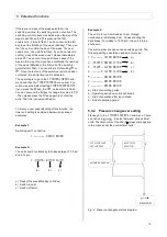
This function allows the operator to externally switch
the compressor on and off. You have two ways of
implementing this function. The remote start / stop
function is permanently programmed. This relates to
terminals X2:1 and X2:3 (see circuit diagram).
The unit continues to run while the potential-free
contact is closed. If the contact is opened, the soft-stop
is undertaken and the unit stops.
Note
The unit is controlled using the remote start / stop
function. If the unit is shut down during operations, e.g.
due to power loss, it does not automatically start up
when the power is restored. The potential-free contact
must first be re-opened and then closed to restart the
unit.
1st option
The compressor is to be activated using a potential-free
contact.
You activate this function in the
[
CONTROL
MENU
]
sub-menu. Please go to the
ENABLE
REMOTE-START
menu item. Once you have pressed the
key, the
OFF
value starts to flash. You can now use the
key to
change the value to
ON
. The
symbol appears in the
first display row.
Please connect the potential-free contact that you need
for the remote start / stop function to the X2:1 and X2:3
terminals. This input is permanently programmed for
the remote start / stop function.
If the remote start / stop function is activated, you can
no longer control the machine using the On
I
and
keys on the DELCOS
Pro
. Only the emergency off
button remains activated. The machine can now only be
switched on and off using the potential-free contact.
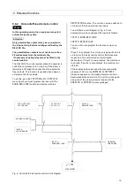
2nd option
A control room is to decide whether the enable for the
remote start / stop function is issued. The function for
the enable is implemented using a digital input. If the
enable is issued, the compressor can only be switched
on and off using the external potential-free contact
(X2:1 and X2:3). If the enable is not issued, the
compressor can only be switched on and off on the
DELCOS
Pro
.
Please connect the potential-free contact that you need
for the remote start / stop function to the X2:1 and X2:3
terminals. This input is permanently programmed for
the remote start / stop function.
In the
[OPTIONAL
IN-/OUTPUTS]
menu you now
have to program one input with the
ENAB.REM-START
function (see section 5.5.1).
The
symbol appears in the first display row. In the
[
CONTROL
MENU
]
sub-menu behind the
ENABLE
REMOTE-START
menu item,
EXT.
appears.
If the input is closed, the unit can only be switched on
and off using the potential-free contact.
If the input is opened, the unit can only be switched on
and off using the DELCOS
Pro
.


