background image

  K-series OEM Board User Guide 


2


1.2 Related documents 

This document only cover frequently used commands, find further information about 
command and log information in 

ComNav OEM Board Reference Manual_V1.5

, also 

for technical specifications of every OEM board model 
Please download at: 

http://www.comnavtech.com/download.asp?bigclassid=27

. 

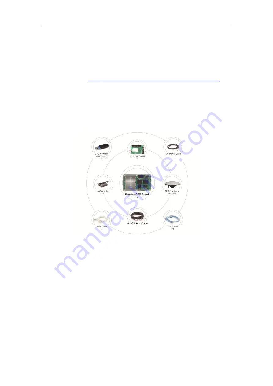
1.3 Evaluation kit


If  you  order  ComNav  Technology  OEM  board  evaluation  kit,  please  check  carefully 
when you receive shipping box as the following figure: 


2.


Installation of K-series OEM board 

This  chapter  introduces  guidelines  to  install  your  OEM  boards,  and  check  status  of 
K-series OEM board. 

2.1 ComNav Technology interface board 

ComNav Technology interface board is a mother board for K-series OEM board, and 
two  types  interface  board  are  available  depending  on  the  size  of  your  OEM  board. 
The following figure shows interface board for small-sized OEM board: 

Summary of Contents for K-series

Page 1: ...K series OEM Board User Guide ComNav Technology User Guide K series OEM Board Version 1 0 2 2017 12 13...

Page 2: ...uide Information in this document is subject to change without notice It cannot be copied or translated into any language without the written permission of ComNav Technology Technical Assistance If yo...

Page 3: ...10 3 6 2 Convert toRINEX 11 3 6 3 Memory Management 12 4 Work mode configuration 12 4 1 Smooth mode 13 4 2 SBAS mode 13 4 3 RTK mode 13 4 4 RTD mode 15 4 5 Moving base mode 16 4 5 1 Moving base statio...

Page 4: ...K series OEM Board User Guide 6 2 Force Update 23...

Page 5: ...s OEM board ComNav Technology K series OEM boards support existing and future constellations which are widely used in high accuracy positioning and navigation applications With QUANTUMTM technology it...

Page 6: ...ion kit If you order ComNav Technology OEM board evaluation kit please check carefully when you receive shipping box as the following figure 2 Installation of K series OEM board This chapter introduce...

Page 7: ...on to the interface board properly Ensure 100 fitting for all connections Firstly unplug the PIN out when uninstalling the OEM cards the K501 installation shown in the following figure 2 Connect the G...

Page 8: ...you to check status of K series OEM board 1 Power indicator of OEM board 2 LED indicators of satellites and correction data Satellite indicator R Flashing N times 5s N the number of satellites tracked...

Page 9: ...municate and configure your OEM boards via serial port or Ethernet connection Download at http www comnavtech com download asp bigclassid 28 3 1Connect with OEM boards For serial port communication Cl...

Page 10: ...for L2 40 42 Glonass R max value for L1 48 50 max value for L2 45 48 Beidou C max value for B1 45 47 max value for B2 45 47 Go to Message to check the output message of receiver Ensure your pc interne...

Page 11: ...ter button at the end of every command to check receivers feedback information or input another command For all programmatic commands please refer to ComNav OEM Board Reference Manual_V1 5 Go to Mode...

Page 12: ...d Anonymous Types OK After receiver received correction data the receiver will calculate the ambiguity and turn to differential mode Go to View PVT View to check RTK status 1 Position mode 2 Different...

Page 13: ...ides two methods to save the raw observation data 1 To save the raw data in the onboard memory For K5 series go to Config select Auto Data log Apply Settings restart your OEM board to activate this se...

Page 14: ...receiver is turned off or its memory runs out 2 if set to 1 2 3 4 12 hours the data recorded will be saved in to a file every 1 2 3 4 12 hours Data log the default setting is manual mode To log data i...

Page 15: ...hrough USB cable and raw data will be saved in the file named after its date 3 6 2 Convert to RINEX After downloading raw observation data to your PC click to convert from ComNav binary format cnb to...

Page 16: ...onfiguration This chapter describes the commands for frequently used work mode which can help you to quick start to use ComNav Technology OEM board ComNav Technology OEM board set single point positio...

Page 17: ...61 E 1 07 2 5 10 4541 M 11 371 M 99 0000 4C 4 2 SBAS mode For ComNav Technology OEM boards the default setting for SBAS is disabled You can enable this mode to improve positioning accuracy if receiver...

Page 18: ...latency time for different constellations if you start base station in radio mode The following commands show RTCM3 0 as an example which may be incompatible with rover receiver of other brands RTCM3...

Page 19: ...put GPGGA message to check if OEM board in RTK mode solution status is E 4 GPGGA 015101 00 3121 0000551 N 12117 5483125 E 4 23 1 1 37 2598 M 0 000 M 02 0004 58 Moreover the default setting is foot mod...

Page 20: ...0 000 M 02 0004 58 4 5 Moving base mode Different from the stationary base station the moving base station transmits corrections to the rover when it s moving Therefore it should set without a fixed p...

Page 21: ...d and one of the OEM boards is used for the dynamic base station Master and the other one is applied as a rover station Slave The settings are used to enable or disable a receiver from working with a...

Page 22: ...f you use K726 or K728 board and two antennas position always fixed you can use the following configuration to restrain the baseline length it will get better azimuth result For example the baseline l...

Page 23: ...he serial port baud rate Com comX 9600 Change the baud rate of comX to 9600 Tip after changing baud rate of current serial port you need to reconnect your OEM board 5 4 Check System Information Log sy...

Page 24: ...comX glorawephemb onchanged Output Glonass ephemeris Log comX bd2rawephemb onchanged Output Beidou ephemeris Log comX rangecmpb ontime 1 Set comX output 1Hz observation data 5 9 High frequency data ou...

Page 25: ...only supports the key words mark1 switch supports the key words enable and disable polarity supports the key words positive and negative which separately represent positive pulse and negative pulse ti...

Page 26: ...half of period Example PPSCONTROL ENABLE POSITIVE 1 1000 5 13 Freset This command clears data which is stored in non volatile memory and set the baud rate to 115200 No data log is outputted Freset Res...

Page 27: ...Guide 23 4 Click Link and Update to upgrade OEMboard Note please don t move your mouse or run other software when updating firmware 5 6 minutes 6 2 Force Update Check the following two options in link...

Page 28: ...K series OEM Board User Guide 24 Tip it s better to use USB to ComNav provided Serial convertor otherwise it may result a fail identify of serial port...

Reviews: