


8
Fastcom
®
: G422/X-PCIe
INSTALLATION
Hardware Installation
Important: Static electricity can harm system boards. Perform service at an ESD workstation and follow
proper ESD procedures to reduce the risk of damage to components. Commtech, Inc. strongly
encourages you to follow proper ESD procedures, which can include wrist straps and smocks, when
handling Fastcom: G422/X-PCIe boards.
1. Turn off PC power. Disconnect the power cord.
2. Remove the PC case cover (if applicable).
3. Unpack the Fastcom: G422/X-PCIe.
4. Select an open PCIe slot in your PC.
5. After removing the blank bracket from your PC, install the Fastcom: G422/X-PCIe in the PC by pressing it
firmly into the slot. Install the bracket screw to hold it firmly in place.
6. Re-install the cover on your PC (if applicable).
7. Refer to Software Installation in the next section for information on installing the software for the board.
Software Installation
The software installation manual is in a separate document. The procedure changes from time to time as we
make improvements.
TESTING THE INSTALLATION
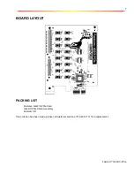
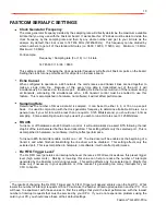
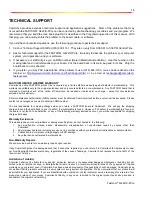
To fully test the installation of your Fastcom: G422/X-PCIe, you will need to build a "loop back plug". Materials
needed are a DB9 male plug, solder-cup style, and two short pieces of 20 or 24 AWG stranded wire. This loop
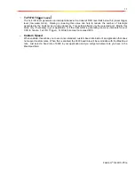
back plug can be used to test any RS-422 port. Jumper the pins together on the DB9 as illustrated below:
Pin 4 Tx +
Pin 5 Tx -
Pin 8 Rx +
Pin 9 Rx -
Testing the Fastcom Async PCI Port in Windows
These instructions assume that you have already installed the card and have followed the installation instructions.
The Device Manager should show the boards/ports that are installed, and the COM numbers assigned to those
ports.
5
4
8
9


