ADCP-93-095 • Rev B • April 2018
Page 5
© 2018, CommScope, Inc.
•
Mounting Brackets—
may be oriented for either 19-inch or 23-inch rack mount.
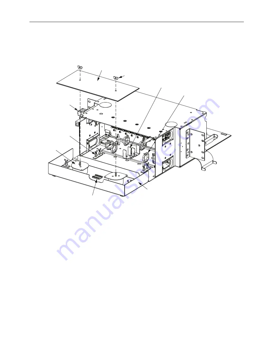
Every LSX Termination/Splice Panel has a rear splice area such as shown in
for the 7-
inch panel. The other height panels have analogous features.
Figure 3. LSX Termination/Splice Panel (Rear View)
The main features in the rear splice area are as follows:
•
OSP or IFC Cable Clamp—
secures cable to chassis.
•
Kurley Locks—
route and secure cable fibers and internal pigtails.
•
Splice Storage Spools—
provides service loop storage for cable fibers and pigtails.
•
Mass Fusion Splice Chip—
splices 24 fiber/pigtail interfaces.
•
Splice Area Access Door—
folds down providing a horizontal splice deck.
•
Cable Ring—
routes and secures cable on entry into splice area.
•
Ribbon Fanout Bracket—
holds one stack of four ribbon fanout chips (if ribbon rather
than stranded pigtails are present).
•
Wing Nut—
secures the cover (next item) to hold it in place.
•
Cover—
protects splices once completed.
Each panel is shipped with a cable clamp.
175
3
1-A
O
S
P OR IFC
CABLE CLAMP
KURLEY LOCK
(TYPICAL)
MA
SS
FU
S
ION
S
PLICE CHIP
WING
NUT
COVER
S
PLICE AREA
ACCE
SS
DOOR
CABLE RING
(TYPICAL)
RIBBON
FANOUT
BRACKET
S
PLICE
S
TORAGE
S
POOL


