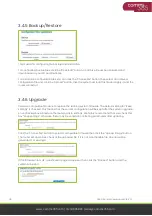
6
C365-5G-Mini User Manual CB-V1.1
www.comms365.com | 01234 865880 | [email protected]
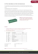
•
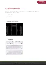
LAN:
LAN RJ45 Ethernet ports.
•
WAN:
WAN RJ45 Ethernet ports.
•
RST:
Sys reset button
•
PWR:
DC power socket. DC5~40V, DC5~50V option depends on the router version
•
VCC:
DC wire positive pole. DC5~40V, DC5~50V option depends on the router version
•
GND:
DC wire ground
•
GND:
Serial ground
•
RX:
Serial receiving
•
TX:
Serial transmission
•
RST:
Reset router
•
DIO0:
Digit I/O port 0
•
IDO1:
Digit I/O port 1
•
NC:
No connection
•
GND:
DC wire ground
•
VCC:
DC wire positive pole. DC5~40V, DC5~50V option depends on the router version
•
WPS:
WPS button
Antenna Connection Table
Antenna Connector
Marks
Cell
for main cell antenna
Aux
for auxiliary cell antenna
Wi-Fi / WLAN
for Wi-Fi antenna
GPS
for GPS antenna
2.3 Installation
The C365-5G-MINI should be installed and configured properly before using. The installation and
configuration should be done under supervision or by a qualified engineer.
Attention:
Do not install or connect/disconnect the cable when its power is turned on.
2.4 SIM/UIM card installation
If your router has a SIM/UIM card protector, please remove it, insert the sim card correctly, and close.
If your router has no SIM/UIM card protector, please insert the sim card correctly.
Attention:
If the SIM/UIM card is not fully inserted, the router cannot identify the card normally.
Please check that the card is fully inserted.


