background image

17

16

* As a common wiring type product, damage may result if the installed Household

videophone unit is removed and installed at a different location. 

* Please turn the unit ON. 
* When damage or malfunction of the unit has been detected, please contact the

Customer Service Center right away. 

* An appropriate circuit breaker must be installed in the building's interior wiring. 
* Do not place vase, water bottles, and etc on top of the unit. 
* Please ensure that electrical power has been completed blocked from the unit when

installing or repairing the unit. 

22. Instruction for use 

When more than one videophone is connected to the system and one of those

videophones are in use, the call cannot be made by another videophone within that

system. 

Also, incoming pages while a call is being made are only heard through the

videophone in which that call is being held from. 

When an emergency situation occurs, emergency alarm will be sounded by all

installed videophones, and the Cancel/Reset feature can only be performed through

videophones supporting that feature. 

This videophone is able to call the guard, wireless phone(ext. 5) and Master

phone(ext. 1) but in other places (common entrance, other households, local loop

and so on), only receiving is available.(Master interlocking function) 

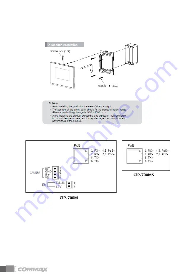
Monitor

T4 X 18

Wall bracket

Mounting Screw

M3 X 8

Monitor

Fixing Screw

Connector

(7P X 1EA)

Adapter

(DC 14V)

Bracket for wall mount

Manual

23. Contents

POWER CORD

16

28

9. INSTALLATION

9.1. 

Installation 

9.2. 

Wiring Diagram and Components 

Precautions when wiring 

1) When installing in the area where the high-voltage line passes around, use the coaxial wire to wire the metal

pipe. 

2) It may be short-circuited if internal wires are exposed due to scratches on the wire sheath, which may cause

malfunction.

3) Turn off the monitor's power switch when connecting the monitor to the camera.

4) The wiring between camera and monitor is polarity.

5) When connecting various sensors, be careful about power and polarity..

Summary of Contents for CIP-700M

Page 1: ...s not responsible for any safety accidents caused by abnormal operation of the product Thank you for purchasing COMMAX products Please carefully read this User s Guide in particular precautions for sa...

Page 2: ...control 16 5 2 Checking multi sensor 16 5 3 Magnetic sensor monitoring 17 5 4 Adding devices 17 5 5 Edit device 18 6 Scenario schedule setting 19 7 Convenient function 23 7 1 Calculator 23 8 Setting 2...

Page 3: ...it may cause an electric shock fire when using a damaged power cable Please don t handle the power cable with a wet hand It may cause an electric shock Please plug out the power cable from the socket...

Page 4: ...power cable Please don t use any chemical products such as wax benzene alcohol or cleanser Please don t drop the product on the ground and don t apply a shock It may cause a failure Please use the de...

Page 5: ...t component Touch Screen Speaker Emergency button Guard button Door open button Call button Home button Microphone Power switch Connection terminal 1 2 Screen composition The bottom button of home scr...

Page 6: ...i Add Wi Fi directly When the Wi Fi you want is not discovered you can add it entering the Wi Fi information directly to the list Select Add Wi Fi network at the bottom of Wi Fi list Enter SSID of net...

Page 7: ...select Registration button 5 Your sign up is completed Edit Initialize 1 If your ID is registered your information will be shown To change the password select P W Change button 2 If you want to delete...

Page 8: ...to make a call 4 When you click Refuse button the call is disconnected 5 When the call is connected the entrance screen is shown 6 If you press Open Door button a warning message will be displayed If...

Page 9: ...tor communication Call log To check Call log Emergency Home emergency button APPs All installed apps list f If you press and hold the home screen for about 1 second you will get a menu that allows you...

Page 10: ...5 Press OK button to save the background Press Close button to cancel editing 2 3 Place Delete device icon on home screen 1 Press and hold the Home screen for about a second 2 Click the Place icon bu...

Page 11: ...n to cancel the pairing connection 5 When the device is registered the device is automatically placed on the home screen 2 5 Place Delete apps on home screen 1 Press and hold the Home screen for about...

Page 12: ...d call screen Activation and waiting call display Setting the front door of our house Connection screen Call volume and volume control Receive a Call Call rejection cancellation Open the door Store vi...

Page 13: ...to cancel monitoring 3 If you want to talk during monitoring press call button 4 Press the End call button Open the door of my house 1 Press the Open Door button during a call 2 Open the door Open com...

Page 14: ...e door Setting my house entrance screen Receive a call at our house 1 Visitor screen are displayed on the wall pad with bell sound when you receive a call 2 Press the Talk reject button to reject the...

Page 15: ...screen and pressing the OK button 3 4 Receive a call via Smartphone Wall pad screen when Smartphone call is connected 1 The image of visitor displayed on screen with a ringing bell 2 Press the Call b...

Page 16: ...ncy button on the front of the product Emergency type is displayed at the top of the screen and a siren sound is generated Emergency stop 1 Press the Stop button at the bottom of emergency alert scree...

Page 17: ...When you press power button of whole lightings all lightings are turned off 4 Press the power button of the lighting you want to control to turn the light on or off Lighting control screen 5 2 Checkin...

Page 18: ...Detected is displayed when door open is detected 3 If no door open is detected No detected is displayed Magnetic sensor screen 5 4 Adding devices 1 Press the button to enter the Add Device mode 2 Pair...

Page 19: ...the device and change the nickname 2 Press OK and then the name of device is changed Device edit screen Remove device 1 Press the Trash button 2 Select the device you want to delete 3 Press the Finis...

Page 20: ...d Scene Main Screen 2 The device selection dialogue window will be displayed if you click Create scene 3 Select the device to set and press the OK button on the upper right corner 4 Select the device...

Page 21: ...y time 3 Press the Close button to cancel the away settings Away mode screen Away delay time Start away mode Items to be run when out If you are setting the security mode away settings will not be exe...

Page 22: ...Sensor use selection Security mode setting 1 Check the security sensor to set by pressing the Security Zone button 2 Press the Apply button to activate the security sensor in the designated zone Secur...

Page 23: ...e scene 2 Press the Edit button to edit the scene 3 You can add and edit device type device attribute scene name and icon on the edit screen 6 6 Scenario Control setting Mode You can perform the desir...

Page 24: ...17 23 7 Convenient function 7 1 Calculator Arithmetic operation You can use the arithmetic calculator function Calculator screen...

Page 25: ...y screen 3 Enter the new password again 4 If the entered password matches the new password will be changed Initial password is 1234 8 3 Connect to COMMAX Settings COMMAX Connect You can set up environ...

Page 26: ...et Data button to reset data such as Visitor Log Visitor Image Call Log Emergency Log 3 Data cannot be restored after initialization 8 4 General setting Setting the ring tone Set up COMMAX Bell sound...

Page 27: ...connect Wi Fi You can reset the network information that was previously connected or currently connected so that it is not automatically connected Select the currently connected Wi Fi and tap Do not s...

Page 28: ...ur current city from the list 24 hour formatting 1 Check or uncheck Use 24 hour format 2 When checked the time is displayed as 24 hours When unchecked displays in 12 hour format Formatting dates 1 Pre...

Page 29: ...use the coaxial wire to wire the metal pipe 2 It may be short circuited if internal wires are exposed due to scratches on the wire sheath which may cause malfunction 3 Turn off the monitor s power swi...

Page 30: ...pun hssGiyhjrl tvup vyGOjpwT WWtP wOXlhPVYwOXlhP jvuulj vy thu hs O PG G GX_ hssGiyhjrl G tv u punGzjyl O lhP zjyl OXlhP OtPGZG G tvup vyGmp pun hssGiyhjrl tvup vyGOjpwT WWtzP thu hs O PG G GX_ hssGiy...

Page 31: ...dBm 1 PER 802 15 4 Section 6 5 3 3 Transmit power 2 5dBm Z Wave data rates 250kbps Frequency bands 2400MHz 2485MHz Supply voltage range 2 0V to 3 6V RF Range 10 75m range Less than 75m 1mW 0dBm Model...

Page 32: ...31 11 System Diagram...

Page 33: ...Printed In Korea 2016 03 104 513 11 Sangdaewon dong Jungwon gu Seongnam si Gyeonggi do Korea Int l Business Dept Tel 82 31 7393 540 550 Fax 82 31 745 2133 Web site www commax com...

Reviews: