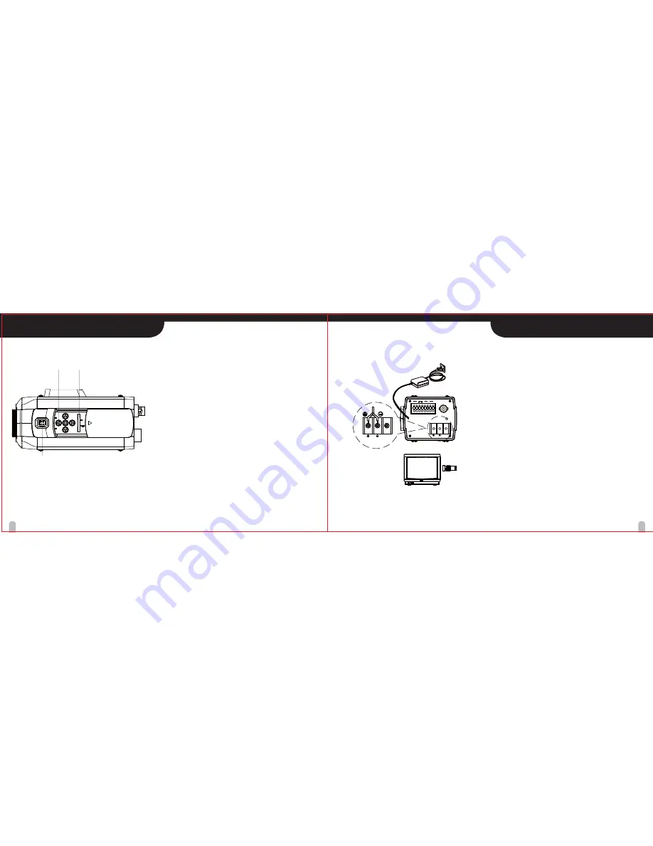
Basic connection
The peripheral devices (DVR, monitor, lens, etc), AC/DC
adaptor and cables are not supplied.
1. Connecting the monitor.
Make the video signal connection between the camera
and the monitor or time lapse monitor or DVR.
2. Use a commercially available AC 24V / DC12V
adaptor.
Connect an AC 24V / DC 12V power source to the
AC 24V / DC 12V input terminal on the back of the
camera.
3. Insert the plug of this power cord into a wall outlet.
The POWER indicator will light. Adjust the picture on
the monitor using the Brightness and Contrast controls
etc.
To monitor’s Video Input
or Camera Input
12
13
PART NAMES AND FUNCTIONS
CONNECTIONS
* DUAL TYPE (Optional)
【
8
】
Buttons for menu
To set items on the MENU, use the these buttons
on the back panel. (page 21)
【
9
】
ALC Lens Setting Switch
·
DC : When you attach an Auto Iris lens requiring
the DC control signal, please put this switch in
the DC position.
·
Video : When you attach an Auto Iris lens requiring
the video control signal, please put this switch in
the VIDEO position.
【
10
】
Lens iris output connector (LENS)
4-pin connector for Video or Auto iris lens.
Note :
Lens selection can be DC or Video.
·
DC : Direct Drive Lens
·
Video : Video Drive Lens
* Fixed Lens does not require Lens selection of DC or Video.
* Refer to your Lens Manual for Instructions and Type.
【
10
】
【
9
】
【
8
】
1
2
3
DC12V/AC24V
FG
POWER
VIDEO OUT
RS-485 ALARM D&N
GND OUT GND
EXT
BALUN
BAL(-)BAL(+)
DC12V/AC24V
FG


