2
Note:
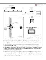
For LPM1 series option placement is only
recommended for Hollow metal doors. For wood doors, use
standard placement above ceiling tile or in junction box.
Module
Ceiling Tile
LPM1 Series Installation
Example
Mod
ule
Standard Placement
Hinge Pocket
Option Only
Standard Placement
Optional Placement
1. The door must be prepared with a standard type 86 mortise lock preparation and a 3/8” wire
raceway. Be sure that the mortise pocket and the raceway are clear of debris prior to installation.
2. Install the 3-prong, 72” wire harness through the wire raceway leaving enough slack to “quick
connect” to the mortise chassis.
3. Install PM300 at the hinge jamb side of the door within 120” of the lockset. Connect the 3-prong wire
harness to the PM300 and hard wire it directly to the harness from the lockset (if using an electric
hinge or other transfer device, use 18ga wire).
4. Connect the 2-prong input power wires (BLACK and BLACK) of the PM300 to the 2-prong, 72” wire
lead. Then connect the 72” wire lead directly to the wire run coming from the 26.5VDC power supply
(not included). The power supply may be up to 300 feet away (see power supply wiring instructions).
Note: these wires are not polarity sensitive.


