


22
23
Operation precautions
We recommend following the boot sequence below.
1. Plug one end of the USB cable into the motherboard connector and the other one to the computer, then
boot the computer.
Start the Candle program and verify in the status window that no errors are showing. Normally, it will show
"Idle". If an "Alarm" error is showing, with your mouse, click the Candle "Reset" then "Unlock " buttons in
that order to get to the "Idle" condition.
3. Connect the 24V/5A power adapter and turn on the controller board with the "O/I" button in white
letters.
4. Next, click on the "Spindle" button to turn on the spindle motor. Set "Feed:" to 500.
5. Click on the left set of direction buttons with the mouse to verify that the X and Y axes are moving
properly. Similarly, click on the right most up and down buttons to verify that the Z-axis moves properly. If
all of these tests are completed properly, your CNC machine is assembled and wired correctly. Shutting
down the machine for use is done in the opposite way to the start-up process.
6. Turn off the controller board with the white letter "O/I" button.
7. Unplug the 24V/5A power adapter.
Shut down the Candle program. Turn off the computer.
Please check to make sure the CNC machine is assembled and wired correctly first, then start the
machine test run.
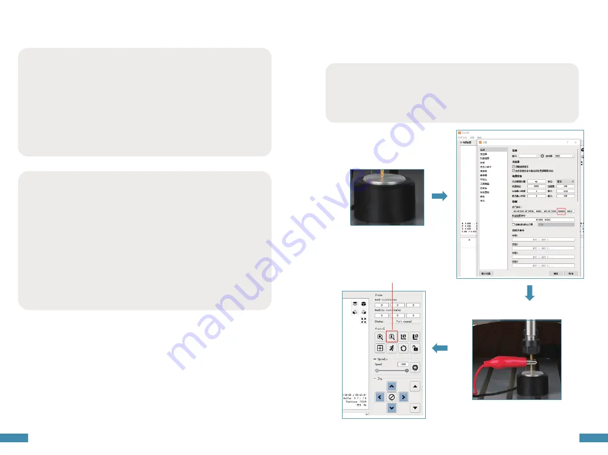
Tool setting gauge block
The use of tool setting instrument is very convenient for users to determine the working zero position of
Z-axis, when tool setting is completed, the system will confirm the current Z-axis position as the zero point
of Z-axis working coordinate system.
Z-axis tool setting button
1. Measure the thickness of the tool setting gauge block
2. Modify the tool setting parameters in the Candle software settings and click OK.
(You must input the thickness of the tool setting gauge into the parameters, and the system will
automatically shift the zero position down to the depth of the thickness of the tool setting gauge when
executing the file, so that the Z-axis working zero point is really determined).
3. Connect the tool setting instrument block cable to the main board plug, and clamp the chuck to the
carving tool shank part.
4. Press the button to execute the tool setting command.
Spindle stop in the middle
Possible causes :
1.Emergency stop button is not reset. If the candle software interface feedback error 3 or error 9, it means
that the emergency stop button is not reset, manually reset can be.
2.The machine is now in laser mode. please change the laser engraving mode to CNC milling engraving
mode, you try to AB two gears are set to the top, dial the paddles to adjust the mode (two paddles all up
for milling engraving mode, and vice versa for laser engraving mode). Use LaserGRBL or lightburn software
to connect to the machine, enter $32=0 in the command bar to adjust to the milling mode. $32=1 for laser
mode (the main board of the machine is miter mode at the beginning, so you only need to adjust the gear,
no need to change the command).
3.Trigger limit switch. Check whether the xyz axis triggers the limit switch, click reset and unlock after the
candle control software is connected to the machine.
candle unlock https://www.youtube.com/watch?v=XIWYfNnniBM.
Handle unlock https://www.youtube.com/watch?v=bSJPHyufEXg.
4.spindle motor overload trigger mos tube current limiting protection device. MOS limit start current is
expected to be around 0.8A (spindle stable current at 0.5A), due to the motor instant start current is very
large (1.5 ~ 2A), for safety reasons, the adapter has 7A current protection, when the current is too large
mos tube will trigger the protection function automatically power off.
If the spindle stops during operation, the following four suggestions can be followed to solve it.
Summary of Contents for CNC Carving Machine
Page 1: ...User Manual V1 1...


