background image

16

099435

3. Pressurize supply piping system by either using compressed air or

opening propane supply tank valve.

4. Check all joints of gas supply piping system. Apply mixture of liquid soap and

water to gas joints. Bubbles forming show a leak.

5. Correct all leaks at once.

Test Pressures Equal To or Less Than 1/2 PSIG

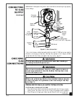
1. Close manual shutoff valve (see Figure 14).
2. Pressurize supply piping system by either using compressed air or opening

propane supply tank valve.

3. Check all joints from propane supply tank to manual shutoff valve (see Figure

15). Apply mixture of liquid soap and water to gas joints. Bubbles forming
show a leak.

4. Correct all leaks at once.

PRESSURE TESTING HEATER GAS CONNECTIONS

1. Open manual shutoff valve (see Figure 14).
2. Open propane supply tank valve.
3. Make sure control knob of heater is in the OFF position.
4. Check all joints from manual shutoff valve to control valve (see Figure 15).

Apply mixture of liquid soap and water to gas joints. Bubbles forming show a
leak.

5. Correct all leaks at once.
6. Light heater (see Operating Heater, pages 17 through 20). Check the rest of the

internal joints for leaks.

7. Turn off heater (see To Turn Off Gas to Appliance, page 20).
8. Replace front panel.

ON

POSITION

OFF

POSITION

Figure 14 - Manual Shutoff Valve

Manual
Shutoff
Valve

Open

Closed

CHECKING

GAS

CONNECTIONS

Continued

Figure 15 - Checking Gas Joints

Propane
Supply Tank

Manual
Shutoff
Valve

Control Valve Location

Summary of Contents for CGP16R

Page 1: ...or use gasoline or other flammable vapors and liquids in the vicinity of this or any other appliance WHAT TO DO IF YOU SMELL GAS Do not try to light any appliance Do not touch any electrical switch do...

Page 2: ...burns fire explosion electrical shock and carbon monoxide poisoning WARNING ICON G 001 DANGER Carbon monoxide poisoning may lead to death Carbon Monoxide Poisoning Early signs of carbon monoxide pois...

Page 3: ...entilation to run properly This heater has an oxygen depletion sensor ODS pilot light safety system The ODS shuts down the heater if not enough fresh air is available See Fresh Air for Combus tion and...

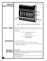
Page 4: ...s or other sources to light heater LOCAL CODES Install and use heater with care Follow all local codes In the absence of local codes use the latest edition of National Fuel Gas Code ANSI Z223 1 also k...

Page 5: ...The air that leaks around doors and windows may provide enough fresh air for combustion and ventilation However in buildings of unusually tight construction you must provide additional fresh air Unus...

Page 6: ...r Gas furnace ___________________ BTU Hr Vented gas heater ___________________ BTU Hr Gas fireplace logs ___________________ BTU Hr Other gas appliances ___________________ BTU Hr Total ______________...

Page 7: ...or on the wall connecting the two spaces see options 1 and 2 Figure 2 You can also remove door into adjoining room see option 3 Figure 2 WARNING ICON G 001 WARNING Rework worksheet adding the space of...

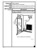
Page 8: ...en to the outdoors These spaces include attics and crawl spaces Follow the National Fuel Gas Code NFPA 54 ANSI Z223 1 Section 5 3 Air for Combustion and Ventilation for required size of ventilation gr...

Page 9: ...nces shown in Figure 4 page 10 If you can provide greater clearances from floor ceiling and joining wall You can locate heater on floor away from a wall An optional floor mounting stand is needed Purc...

Page 10: ...NING ICON G 001 CAUTION If you install the heater in a home garage heater pilot and burner must be at least 18 inches above floor locate heater where moving vehicle will not hit it For convenience and...

Page 11: ...vides the strongest hold Insert mounting screws through mounting bracket and into wall studs Attaching to wall anchor This method allows you to attach mounting bracket to hollow walls wall areas betwe...

Page 12: ...holes drilled in wall 3 Insert mounting screws through bracket and into wall studs 4 Tighten screws until mounting bracket is firmly fastened to wall studs Attaching to wall anchor method For attachin...

Page 13: ...talling Bottom Mounting Screws 1 Locate two bottom mounting holes These holes are near bottom on back panel of heater see Figure 11 2 Mark screw locations on wall 3 Remove heater from mounting bracket...

Page 14: ...ou do not reduce incoming gas pressure heater regulator damage could occur Install external regulator with the vent pointing down as shown in Figure 12 Pointing the vent down protects it from freezing...

Page 15: ...t heater and its individual manual shutoff valve from gas supply piping system Pressures in excess of 1 2 psig will damage heater regulator 2 Cap off open end of gas pipe where manual shutoff valve wa...

Page 16: ...ming show a leak 4 Correct all leaks at once PRESSURE TESTING HEATER GAS CONNECTIONS 1 Open manual shutoff valve see Figure 14 2 Open propane supply tank valve 3 Make sure control knob of heater is in...

Page 17: ...turn the gas control knob Never use tools If the knob will not push in or turn by hand don t try to repair it call a qualified service technician or gas supplier Force or attempted repair may result i...

Page 18: ...d turn it counterclockwise C clockwise to the PILOT IGN position This will light pilot Note You will hear a loud click when the control knob reaches the PILOT IGN position If pilot does not light turn...

Page 19: ...st heating levels by using the manual shut off valve GRH OV 023A BURNER PATTERNS VANGUARD NON T STAT PLAQUE MODELS LOW OFF PILOT IGN MED OFF PILOT IGN HIGH OFF PILOT IGN OFF OFF HIGH MED LOW Control K...

Page 20: ...e control knob TO TURN OFF GAS TO APPLIANCE If pilot flame pattern is incorrect as shown in Figure 20 turn heater off see To Turn Off Gas to Appliance above see Troubleshooting pages 22 through 25 INS...

Page 21: ...s incorrect as shown in Figure 22 turn heater off see To Turn Off Gas to Appliance page 20 see Troubleshooting pages 22 through 25 Figure 21 Correct Burner Flame Pattern INSPECTING BURNER Continued BU...

Page 22: ...passageways of heater clean Inspect these areas of heater before each use Have heater inspected yearly by a qualified service person Heater may need more frequent cleaning due to excessive lint from...

Page 23: ...ROBLEM When control knob is pressed in and turned to the PILOT IGN position there is spark at ODS pilot but no ignition ODS pilot lights but flame goes out when control knob is released POSSIBLE CAUSE...

Page 24: ...et between locked positions 1 Residues from manu facturing processes 1 Metal expanding while heating or contracting while cooling REMEDY 1 Clean burner orifice s see Cleaning and Maintenance page 22 o...

Page 25: ...age 2 Control valve defec tive 1 Foreign matter be tween control valve and burner 2 Gas leak See Warn ing statement at top of page OBSERVED PROBLEM Heater produces unwanted odors Heater shuts off in u...

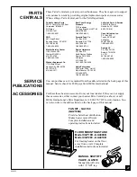
Page 26: ...RVICE HINTS REPLACEMENT PARTS Note Use only original replacement parts This will protect your warranty coverage for parts replaced under warranty Parts Under Warranty Contact authorized dealers of thi...

Page 27: ...82 215 696 2670 1 800 368 0803 LaPorte s Parts Service 2444 N 5th Street Hartsville SC 29550 803 332 0191 Cans Unlimited Inc P O Box 645 Taylor SC 29687 All States 803 879 3009 1 800 845 5301 Dealers...

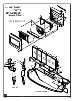
Page 28: ...HEATER EXPLODED VIEW ILLUSTRATED PARTS BREAKDOWN Model CGP16R 13 15 13 14 ODS PILOT BURNER ASSEMBLY A B C 13 1 13 2 13 3 13 10 13 4 13 5 13 6 13 7 13 8 13 9 13 12 13 13 13 11 1 2 3 11 6 4 8 5 6 7 12 1...

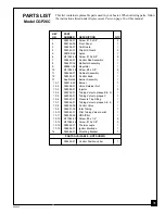
Page 29: ...8 2 11 098455 01 Cabinet Assembly 1 12 098324 01 Control Knob 1 13 See Detail Burner Assembly 1 13 1 099218 01 Burner 1 13 2 098508 01 Valve Retainer Nut 1 13 3 099056 01 Injector 3 13 4 099048 01 Tub...

Page 30: ...ATER EXPLODED VIEW ILLUSTRATED PARTS BREAKDOWN Model CGP26C 13 15 13 14 ODS PILOT E D C 13 1 13 2 13 3 13 9 13 4 13 5 13 7 13 6 13 8 13 10 13 12 13 13 13 11 B A 1 2 3 11 6 13 4 8 5 6 7 12 9 10 14 BURN...

Page 31: ...0 M11084 38 Screw 8 x 3 8 2 11 098456 01 Cabinet Assembly 1 12 098324 01 Control Knob 1 13 See Detail Burner Assembly 1 13 1 099218 02 Burner 1 13 2 098508 01 Valve Retainer Nut 1 13 3 099056 01 Injec...

Page 32: ...ed by a qualified installer in accordance with all local codes and instructions furnished with the unit This warranty does not apply to parts that are not in original condition because of normal wear...

Reviews: