IOM - TRUNNION BALL VALVES, UNIFLOW® BV BT-B9
©COMEV
AL
V
AL
VE SYSTEMS
Technical Dept. Ref. IOM - UNIFLOW BV BT
-B9 - Ed.18/03
Comeval V
alve Systems reserves the right to alter any technical data contained in this Manual without prior notice. Regularly updated data on www
.comeval.es
Page 3
4.4 Technical data – remarks
Check valve selection, material compatibility, pressure and temperature limits and other essential parameters. Ensure
proper safety devices/measures are implemented to prevent exceeding intended use of the product. Contact the ma-
nufacturer for advice in case of pressure tests exceeding the intended use. Refer to Data Sheet for data such as main
features, duties/limits of use, dimensions, weights, etc. and consult the manufacturer for further information.
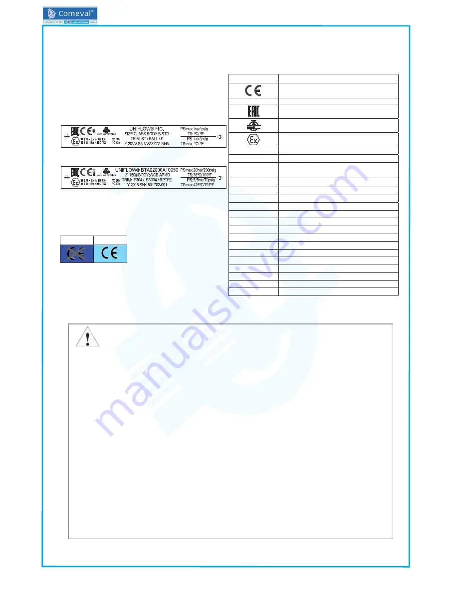
4.5 Marking/nameplate
Nameplate description of the valve:
4.6 marking
* See coding system on Data Sheet.
5. – INSTALLATION
5.1 General remarks on installation
The following points should be taken into account in addition to the general principles governing installation work:
ATTENTION!
- Before installation, make sure previous chapters are thoroughly followed.
- Ensure safe access and working conditions for proper performance.
- Only operate the valve while observing all the safety measures.
- Remove flange covers or any other remaining packing/storage protection if present.
- Lay pipelines such that damaging transverse, bending and torsional forces are avoided.
- Protect valves from dirt during construction work. The interior of the valve and the pipeline must be free of foreign
particles.
- Protect the valve soft parts from heating caused by welding works at the plant during commissioning.
- Avoid mechanical damage to the seats and ball.
- Valves are normally bidirectional. Some special designs are unidirectional, in such a case please follow the arow
in the body for flow direction. Valve optimal position is horizontal with stem pointing upwards. Valves can alterna
-
tively be installed in vertical pipelines. Try to avoid the stem pointing downwards.
- When using the valve as an end seal, the employers’ liability insurance association of the gas and waterworks
specifies the use of a safety precaution such as a plug-in disc, blind flange, etc. With a medium jet that freely exists,
you must secure the exit area.
- Valves should be installed with ball in open position
- When the valve is operated, there is a crushing hazard between the ball and the seats. Ensure the valve is not
under operation in case hands are introduced inside the valve.
- When installing the valve, there is a crushing hazard between valve and pipe system. Mind the hands to avoid it.
Flanged ends valves:
- Make sure that counterflanges are compatible with the standard of the valve flanges. When matching up flanges,
avoid gradients, rotation and pipe misalignment that could cause pipe and valve stress and leakage once installed.
Flanges should fit smoothly. Select the proper flange face gaskets according to duty and centre them on the flange
face properly. Do not force the counterflanges and do not try to tighten the bolts when a gap exists between valve
and pipe or if misalignment is observed. Tighten in a crosswise, moderate and uniform manner.
DN≤25
DN>25
Mark
Description
CE-Marking
NB
Number of notify body
EAC marking (compliance with
TR/CU 032/2013 & TR CU 010/2011)
Manufacturer logo
Explosion protected mark for EU free circulation
(see separate instructions for code)
www.comeval.es
Website of manufacturer
UNIFLOW®
Brand
PED 2014/68/EU
Directive 2014/68/EU
FIG.
Valve code*
SEP
Sound Engineering Practice
Y.20VV
Manufacturing year
SN: VVZZZZZ-N
Batch / Serial no.
SIZE
Valve size
CLASS
Valve class
B
Body material
STD
Main manufacturing standard
ST
Stem material
BALL
Ball material
S
Seat material
PSmax
Max. pressure
TS
Max. temperature at max. pressure
PS
Max. pressure at max. temperature
TSmax
Max. temperature


