background image

IOM -


SELF-ACTING DIAPHRAGM VALVES 

MAXOMATIC VMXBERL24C 

©COMEV

AL

 V

A

L

VE SYSTEMS 

T

echnical Dept. Ref. IOM-SELF-ACTING DIAPHRAGM V

A

L

VES, MAXOMA

TIC VMXBXERL24C-Ed.15/05

Comeval V

alve Systems reserves the right to alter any technical data contained in this Manual without prior notice. Regularly u

pdated data on www

.comeval.es

8. – TROUBLESHOOTING

In the event of malfunction or faulty operating performance, check that the installation and adjustment work has been 
carried out and completed in accordance with this Manual.

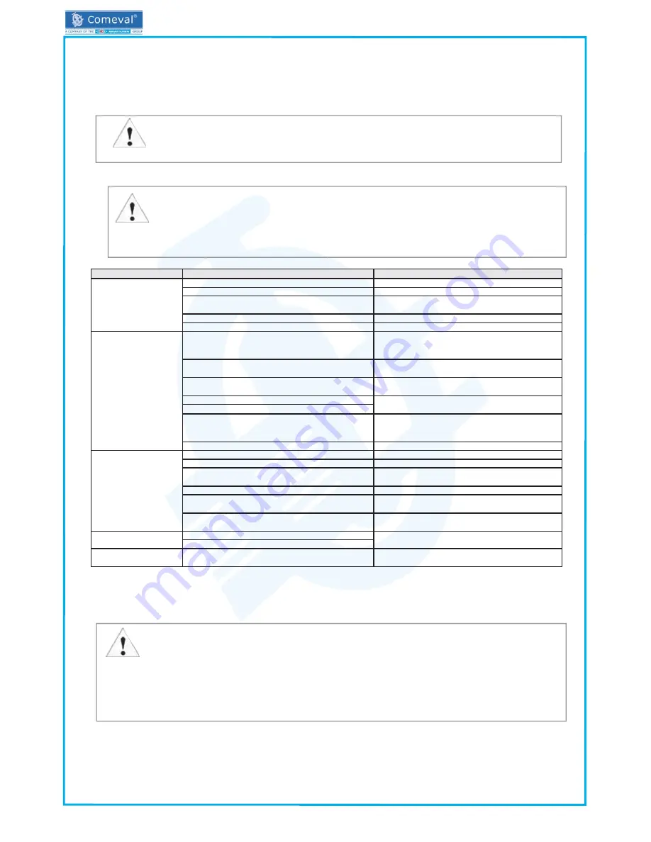
9. – TROUBLESHOOTING TABLE

FAULT

POSSIBLE CAUSE

CORRECTING MEASURES

No fl ow          
Not enough fl ow

-Flange covers or protection not removed.

-Clear valve entrances.

-Isolating valves of Pilot circuit or of pipeline closed.

-Open the valves.

-Normal pipeline pressure is not enough to overcome 
diaphragm rigidity.

-Check pipeline pressure in relation to selected dia-
phragm and the condition of the diaphragm itself.

-Piping clogged.

-Check piping system.

-Solenoids calcifi ed or with impurities.

-Check the Solenoid clean or replace if needed.

Valve is not closing or is 
not tight at closing

-The Pilot is not operating correctly or is not well ad-
justed. The Pilot does not stop the drainage of the 
activation chamber (observe the exhaust of the Pilot).

-Check the closing with the manual valve or with the 
Solenoid valve if any.

-Check adjustment and condition of the Pilot. Chan-
ge if needed.

-Dirt/deposits trapped between the diaphragm and 
body seat.

-Open and close again trying to eliminate dirt trap-
ped.

-Diaphragm damaged.

-Disassemble and inspect the body and diaphragm, 
clean or replace parts.

-Body seat wear.
-Strainer or Pilot circuit clogged.

-Check  if  the  fl uid reaches the activation chamber, 
by unplugging the corresponding connection. Revise 
fi ltering and Pilot circuit. 

-Solenoids calcifi ed or with impurities.

-Check the Solenoid core, clean or replace if needed.

Valve is not regulating 
properly

-Pilot is not well adjusted.

-Check tightening of Pilot adjusting screw.

-Valve is oversized.

-Check valve sizing.

-The adjusting point is out of the Pilot adjusting range 
or out of the diaphragm working range.

-Check operation conditions in relation to Pilot and 
diaphragm. 

-Strainer or Pilot circuit clogged.

-Check fi ltering and Pilot circuit.

-Pilot working failure.

-Tighten/loosen the Pilot adjusting screw to observe 
if there is any reaction. Inspect/replace it if needed.

-Opening/closing speed not suitable (large size val-
ves with accelarator Pilot).

-Check adjustment of adjusting screw of accelerator 
Pilot.

Broken fl ange

-Bolts not properly tightened.

-Realign piping and fi t new valve.

-Mating fl anges not properly aligned.

Leakage between body 
and cover

-Cover bolts loose or diaphragm damaged.

-Retighten bonnet bolts or change diaphragm.

Technical support always available through our website www.comeval.es or your local distributor.

10. – DISMANTLING THE VALVE OR THE COVER

Page 7


ATTENTION!

- Read chapters 10 & 11 before carrying out installation and repair work!
- Read chapter 6 before recommissioning!


ATTENTION!

The following points must be observed:
- Pressureless pipe system
- Medium must be cool
- Plant must be drained
- Purge pipe systems in case of toxic, corrosive, fl ammable or caustic media


ATTENTION!  

- It is essential that the safety regulations are observed when identifying faults.

Summary of Contents for MAXOMATIC Series

Page 1: ...OTES ON POSSIBLE DANGERS 2 2 1 Significance of symbols 2 2 2 Explanatory notes on safety information 2 3 0 PRESERVATION STORAGE AND TRANSPORT 2 4 0 DESCRIPTION 2 4 1 General Description Operating Principles 2 4 2 Area of Application 3 4 3 Technical data remarks 3 4 4 Marking nameplate 3 5 0 INSTALLATION 3 5 1 General remarks on installation 3 5 2 Assembling additional modules 4 5 3 Requirements at...

Page 2: ...turn can cause serious injury to persons or damage to property 3 PRESERVATION STORAGE AND TRANSPORT ATTENTION Use proper packing for transportation Keep storage protection before installation The valve surface is protected by an epoxy paint In order to prevent damage corrosion or rust on the surface avoid ex treme temperatures keep at 5ºC to 50ºC avoid high environmental humidity or corrosive envi...

Page 3: ... covers or any other remaining packing storage protection if present The interior of the valve and the pipeline must be free of foreign particles The valve is unidirectional Follow the arrow in the cover for installation Lay pipelines such that damaging transverse bending and torsional forces are avoided Protect valves from dirt during construction work Protect the valve soft parts from heating ca...

Page 4: ...under operation in case hands are introduced inside the valve When the valve discharges to atmosphere we recommend to set an orifice plate downstream of the valve properly sized to control the flow rate and minimize cavitation This will also help to diaphragm opening and will ease foreign particles removal When using the valve as an end seal the employers liability insurance association of the gas...

Page 5: ...gh velocities as refe rence max 4 m s or lower in case of abrasive media Prevent pulsing flow or water hammers which are very harmful for valves and the rest of the components Flooding of the product is not recommended Allow enough space for valve installation operation and maintenance It is recommended to install a proper sized mesh strainer upstream the valve in order to protect seating surfaces...

Page 6: ...rd obstructions or blocking in the Pilot system Check the valve surface inside and outside and retouch coating protection when needed If advanced corrosion or ero sion is observed double check service and valve features and replace the valve properly In case of body cover leakage retighten the bolts in a crosswise moderate and uniform manner If leakage cannot be corrected dismount the cover clean ...

Page 7: ...d inspect the body and diaphragm clean or replace parts Body seat wear Strainer or Pilot circuit clogged Check if the fluid reaches the activation chamber by unplugging the corresponding connection Revise filtering and Pilot circuit Solenoids calcified or with impurities Check the Solenoid core clean or replace if needed Valve is not regulating properly Pilot is not well adjusted Check tightening ...

Page 8: ...ng from those laid down by specifications or other agreements Justified complaints will be eliminated by repair carried out by us or by a specialist appointed by us No claims will be accepted beyond the scope of this warranty The right to replacement delivery is excluded The warranty shall not cover maintenance work Our guarantee coverage does not cover for any commissioning maintenance or install...

Page 9: ... 05 Comeval Valve Systems reserves the right to alter any technical data contained in this Manual without prior notice Regularly updated data on www comeval es 12 LAYOUT AND PARTS LIST Page 9 Nº PART 1 Body 2 Cover 3 Diaphragm 4 Bolts nuts 5 Valve 4 way 6 1 Solenoid 24Vdc 6 2 Solenoid latch 7 Pilot 8 Nameplate 9 Tubing 10 Inner strainer LAYOUT MAIN PARTS ...

Reviews: