Instructions and operating manual sweeper CSW 1200 B - CSW 1200 G (translated from original instructions)
pag. 40
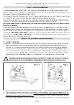
EQUIPMENT ON THE CSW 1200 B CONTROL PANEL
1) Gear switch
2) Electric switchboard check led
3) Filter Buzzer Button
4) Acoustic Indicator Button
5) Brushes motor switch
6) Ignition key
7) Working light switch (optional)
8) Charge indicator
9) Hour counter
u
GEAR SWITCH:
Part. 1
The purpose of the gear switch lever is to move the machine forward or
reverse. When the switch is in forward position (arrow pointing up) by pressing
the pedal
Part. 3 Fig. 9
the machine moves forward. When the switch lever is in
reverse position (arrow pointing down) by pressing the pedal the machine moves
reverse.
For safety reasons, the reverse speed is very low.
If the switch is left in
central position, the machine moves neither forward nor in reverse.
u
ELECTRIC SWITCHBOARD CHECK LED:
Part. 2
This red led must be always switched on during functioning. If this led
should flash at regular intervals there could be technical problems within the ma-
chine. In this case you are adviced to immediately contact assistance to check the
motor sweeper.
u
FILTER BUZZER BUTTON:
Part. 3
This buzzer cleans the suction filters through a motor-vibrator
Part. 2 Fig.
5;
it must be pressed at least 6 / 7 times for 8 / 10 seconds each (operation to be
performed before starting work, before emptying the bin and with the motor off);
to perform this operation with motor running, close the suction by pulling the
knob
Part. 1 Fig. 6.
u
ACOUSTIC INDICATOR BUTTON:
Part. 4
By pressing this button the acoustic indicator switches on.
u
BRUSHES MOTOR SWITCH:
Part. 5
By actioning this switch either central and side brushes are activated.
u
IGNITION KEY:
Part. 6
It activates the switchboard and in particular the movement potentiometer. It is therefore possible to
move the machine without have it working.
u
WORKING LIGHT SWITCH (optional):
Part. 7.
It activates the adjustable working light.
u
CHARGE INDICATOR:
Part. 8
It indicates the charge level of batteries and it’s represented by three coloured lights (red, yellow and
green); by turning on the ignition key
Part. 6
they switch on in the following order: red-yellow-green;
wait un-
til green light is on before forwarding or reversing.
If red light should switch on batteries need recharging.
IT IS RECOMMENDED NOT TO WAIT UNTIL THE RED LIGHT TURNS ON TO PROCEED WITH
RECHARGING OF BATTERIES BUT TO PROCEED WITH THE OPERATION AS SOON AS YELLOW
LIGHT SWITCHES ON.
CSW 1200 B
Fig. 10
Summary of Contents for 9302 0001
Page 4: ......
Page 58: ...CSW 1200 B CSW 1200 G 58 7...
Page 59: ...CSW 1200 B CSW 1200 G 59 5 Honda...
Page 60: ...CSW 1200 B CSW 1200 G 60 5 10 45 C...
Page 61: ...CSW 1200 B CSW 1200 G 61 8 u 3 1 2 3 u 1 4 u 2 4 13 25 u 1 5 1 6 4 5 6 3 5 4...
Page 62: ...CSW 1200 B CSW 1200 G 62 u 4 6 u 1 7 2 7 u 1 8 2 8 u 4 9 u Parking 4 9 6 7 8...
Page 63: ...CSW 1200 B CSW 1200 G 63 u 1 6 u 2 6 u 3 9 1 u 3 9 u 1 9 1 9 9...
Page 68: ...CSW 1200 B CSW 1200 G 68 12 1 6 1 8 u 1 6 2 u 1 6 2 u 1 u 5 6...
Page 72: ...CSW 1200 B CSW 1200 G 72 14 CSW 1200 G 1 5 2 5 5 hg 10W 30 3 40 50 4 25 CSW 1200 G OIL ALERT...
Page 73: ...CSW 1200 B CSW 1200 G 73 30 40 13 15 16 17 1 2 3 4 1 2 7 13 CSW 1200 B 13 CSW 1200 G...
Page 74: ...CSW 1200 B CSW 1200 G 74 19 12 18 CSW 1200 B CSW 1200 G...
Page 75: ......


