background image


2.4 Power ON the switch 

The switch has a universal power supply ranging from 100V to 240V AC, 50 ~ 60Hz power 

source.  The  AC  power  connector  is  located  at  the  rear  of  the  unit.  The  switch’s  power 

supply will adjust to the local power source automatically. 


NOTE:


Do not cover or put anything on or surrounding the switch while the Switch is operating.


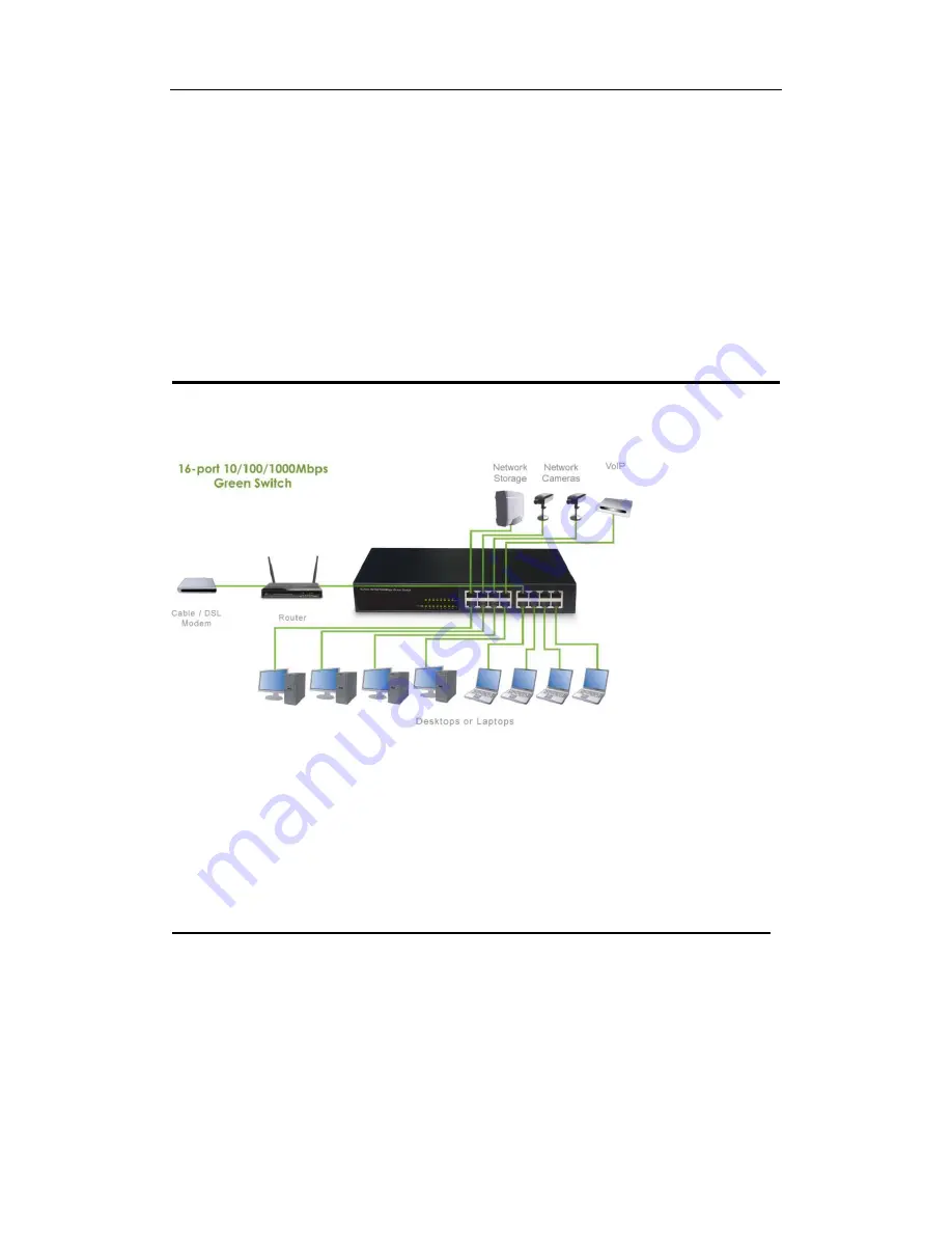
3 Connecting the switch                                                 

This section describes how to connect the switch to your 10/100/1000Mbps Ethernet 

network. 


Figure 3-1  Connecting the Switch 

Your network device (i.e. router, computer, switch, IP Camera, VoIP) can be connected to 

any port of the switch via a two-pair UTP Category 5 Cable or Category 5E Cable. If the 

LED  indicators  do  not  light  up  after  making  a  proper  connection,  check  your  network 

device, the cable, the switch conditions and connections. 


4 Troubleshooting                                                         

1.  Power LED is not lit 


Check if the power cable is properly connected to the power outlet. Make sure the 
power cable is firmly plugged into the power socket of the switch. 

2.  Link/Activity is not lit when connect to 10/100/1000Mbps device 


Check the power switch of the network device attached to the switch; make sure it is 

Summary of Contents for IPSWC160A

Page 1: ...SWITCH 16 GIGABIT PORTS ART IPSWC160A Please read this manual thoroughly before use and keep it for future reference ...

Page 2: ... on into the network Support IEEE802 3az energy efficient Ethernet EEE reduce power consumption by detection cable length and operating loading auto adjust signal intensity Reduce energy consumption protect the environment Before you begin the installation please check the items of your package Package Contents 16 Port 10 100 1000Mbps Green Switch Power Cord User Manual Brackets Screws Rubber feet...

Page 3: ...tors comprehensive LED indicators display the status of the Switch and the network see Section 1 2 3 1 2 2 Rear Panel Figure 1 2 Rear Panel View of the Switch AC Power Connector Supports AC 100 240V 50 60Hz 1 2 3 LED Indicators Information The front panel LEDs provide instant status feedback and help monitoring and troubleshooting when needed Figure 1 3 Front Panel View of the Switch POWER Power I...

Page 4: ...rdy level surface that can support its weight When connecting the power cord to the switch and the power outlet the distance should be no more than the length of power cord Please leave at least 10cm about 4 inches of space at the front and rear of the switch for ventilation 2 2 Desktop or Shelf Installation When installing the switch on the desktop or shelf please attach the rubber feet to the sw...

Page 5: ... 1 Connecting the Switch Your network device i e router computer switch IP Camera VoIP can be connected to any port of the switch via a two pair UTP Category 5 Cable or Category 5E Cable If the LED indicators do not light up after making a proper connection check your network device the cable the switch conditions and connections 4 Troubleshooting 1 Power LED is not lit Check if the power cable is...

Page 6: ...Ethernet Network Cables Ethernet 10Base T cables 2 pair UTP Cat 3 4 5 up to 100m Fast Ethernet 100Base T cables 2 pair UTP Cat 5 up to 100m Giga Ethernet 1000Base T cables 4 pair UTP Cat 5E up to 100m Ports 16 x 10 100 1000Mbps Auto Negotiation RJ45 Port Access Method CSMA CD Transmission Method Store and Forward MAC Address Table 8K Jumbo Frame 9K byte jumbo packet length forwarding at wire speed...

Page 7: ...m 11 x 7 x 1 74 in Weight 1460 g Physical and Environmental Power Input 100 240V AC 50 60Hz Operation Temperature 0 C 40 C Storage Temperature 40 C 70 C Humidity 5 90 RH non condensing Network conditions and environmental factors as well as network overhead can lower actual data throughput rate ...

Reviews: