

2
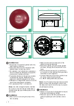
Installazione
• Rimuovere il coperchio agendo sulla clip
dell’incastro posteriore
• Assicurarsi che le frecce impresse sulla
plastica siano rivolte verso l’alto
• Far passare i cavi utilizzando i pressacavi
forniti in dotazione attraverso le apposite
pre-fessure ricavate sulla base
• È possibile fissare la campana su scatola
di derivazione oppure direttamente a
parete con tasselli adeguati (non forniti)
• Effettuare il collegamento (sezione cavi 2,5
mm2 max) rispettando la polarità.
• N°2 pressacavi PG21 in dotazione
Nota:
una volta collegata fissata e testata
rimuovere la vite anti-tamper dalla base e
inserirla nella clip per evitare aperture non
autorizzate
Installation
• Remove the cover using the clip on the
rear coupling.
• Make sure the arrows stamped on the
plastic are facing upwards
• Route the cables, using the cable glands
provided, through the relevant slits in the
base
• The bell can be secured to a junction box
or mounted on the wall itself using suitable
wall anchors (not supplied)
• Connect the wires (wire cross-section max.
2.5 mm2), observing the polarity
• 2 x PG21 cable glands are provided
Note:
once the device has been secured and
tested, remove the anti-tamper screw from
the base and insert it into the clip to prevent
unauthorised opening.
Installation
• Retirer le couvercle en dégageant la clip du
système d’emboîtement arrière
• S’assurer que les flèches gravées sur la
partie en plastique sont tournées vers le
haut
1
2
3
4
150 mm
87 mm
133 mm
95 mm
91,67 mm
91,67 mm
ø 5,15 mm