background image

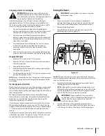
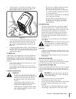
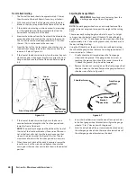
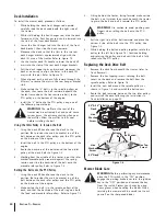
Pivot the operator’s seat forward and clean the reservoir 

1. 

cap and the area around the cap to prevent debris from 
contaminating the transmission oil. See Fig. 6-2.

Turn the reservoir cap counterclockwise to re-move, then 

2. 

check the oil level in the reservoir. Oil should be  visible 
at the bottom of the cup, but the oil level must NOT be 
above 1⁄4” from the bottom of the cup. DO NOT FILL THE 
RESERVOIR.

If necessary to add oil because of some type of leakage, use 

3. 

a quality 20W50 motor oil and add only enough oil to bring 
the level within 1⁄4” of the bottom of the reservoir. Reinstall 
the cap and fully tighten.

Tire Maintenance

Check the tire air pressure after every 50 hours of operation or 
weekly. Keep the tires inflated to the recommended pressures. 
Improper inflation will shorten the tire service life. See the tire 
side wall for proper inflation pressures. Observe the following 
guidelines:

Do not inflate a tire above the maximum pressure shown 

t

on the sidewall of the tire.

Do not reinflate a tire that has been run flat or seriously 

t

under inflated. Have a qualified tire mechanic inspect and 
service the tire.

General Battery Information

8"3/*/(

Should battery acid accidentally splatter into 

t

the eyes or onto the skin, rinse the affected area 
immediately with clean cold water. If there is 
any further discomfort, seek prompt medical 
attention.

If acid spills on clothing, first dilute it with 

t

clean water, then neutralize with a solution of 
ammonia/water or baking soda/water.

NEVER connect (or disconnect) battery charger 

t

clips to the battery while the charger is turned 
on, as it can cause sparks.

Keep all sources of ignition (cigarettes, matches, 

t

lighters) away from the battery. The gas 
generated during charging can be combustible.

As a further precaution, only charge the battery 

t

in a well ventilated area.

Always shield eyes and protect skin and clothing 

t

when working near batteries.

Batteries contain sulfuric acid and may emit 

t

explosive gases. Use extreme caution when 
handling batteries. Keep batteries out of the 
reach of children.

Battery Maintenance

The battery is filled with battery acid and then sealed at 

t

the factory. However, even a “maintenance free” battery 
requires some maintenance to ensure its proper life cycle.

Spray the terminals and exposed wire with a battery 

t

terminal sealer, or coat the terminals with a thin coat of 
grease or petroleum jelly, to protect against corrosion.

Always keep the battery cables and terminals clean and 

t

free of corrosion.

Avoid tipping. Even a sealed battery will leak electrolyte 

t

when tipped.

8"3/*/(

Batteries contain sulfuric acid and may 

emit explosive gases. Use extreme caution when 
handling batteries. Keep batteries out of the reach 
of children.

Lubrication

Using a pressure lubricating gun, lubricate the front castor 

t

wheel axles and the front pivot axle with grease after every 
10 hours of service.

Periodically lubricate all other pivot points with a quality 

t

lubricating oil.

Cleaning the Spindle Pulleys

Once a month remove the belt covers to remove any 
accumulation of grass clippings from around the spindle pulleys 
and V-belt. Clean more often when mowing tall, dry grass.

Using the Transmission Bypass Rods

If for any reason the tractor will not drive or you wish to move the 
tractor, the two hydrostatic transmissions are equipped with a 
bypass rod that will allow you to manually move the tractor short 
distances. 

8"3/*/(

Do not tow the tractor, even with the 

bypass rod engaged. Serious transmission damage 
will result from doing so.

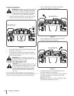
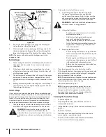
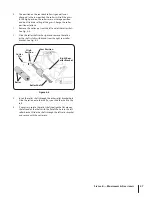
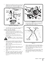
From just in front of the two rear tires, locate the 

1. 

transmission bypass rods. Refer to  Fig. 6-3.

Pull one rod toward the front of the tractor until the flange 

2. 

on the rod is forward of the keyhole slot in the frame 
assembly. 

Lower the bypass rod into the keyhole slot and release so 

3. 

the rod flange is against the front of the frame bracket.

3FTFSWPJS$BQ

'JHVSF

23

S

ECTION

 6 — M

AINTENANCE

 & A

DJUSTMENTS

Summary of Contents for ZT50

Page 1: ...SBOUZ 8 3 3 0 08 4 5 36 4 4536 5 0 4 5 4 6 03 55 15 50 01 3 5 5 4 63 50 0 1 8 5 5 4 4536 5 0 4 3 46 5 1 340 63 3 5 4FSJFT 5SBDUPS PEFMT 5 5 LES DISTRIBUTIONS RVI LIMITÉE 2955 JEAN BAPTISTE DESCHAMPS LACHINE QUEBEC H8T 1C5 MTD LLC P O BOX 361131 CLEVELAND OHIO 44136 0019 OPERATOR S MANUAL 769 04725B 11 02 10 ...

Page 2: ...ecifications designs and equipment without notice and without incurring obligation This product has met the rigid safety standards of the Outdoor Power Equipment Institute and an independent testing laboratory If you have any problems or questions concerning the machine phone your local authorized service dealer Throughout this manual all references to right and left side of the machine are observ...

Page 3: ...these instructions may result in personal injury When you see this symbol 54 8 3 3 This machine was built to be operated according to the safe operation practices in this manual As with any type of power equipment carelessness or error on the part of the operator can result in serious injury This machine is capable of amputating hands and feet and throwing objects Failure to observe the following ...

Page 4: ...neasy on it do not mow it For your safety use the slope gauge included as part of this manual to measure slopes before operating this machine on a sloped or hilly area If the slope is greater than 15 degrees as shown on the slope gauge do not operate this machine on that area or serious injury could result Do Mow up and down slopes not across Exercise extreme 1 caution when changing direction on s...

Page 5: ... jack knife and cause tractor to overturn Service Safe Handling of Gasoline To avoid personal injury or property damage use extreme 1 care in handling gasoline BTPMJOF JT FYUSFNFMZ GMBNNBCMF BOE UIF WBQPST BSF FYQMPTJWF Serious personal injury can occur when gasoline is spilled on yourself or your clothes which can ignite Wash your skin and change clothes immediately Use only an approved gasoline ...

Page 6: ...al equipment specifications may lead to improper performance and compromise safety Do not change the engine governor settings or over speed 12 the engine The governor controls the maximum safe operating speed of the engine Maintain or replace safety and instruction labels as 13 necessary Observe proper disposal laws and regulations for gas oil 14 etc to protect the environment According to the Con...

Page 7: ...he cutting deck Contact with the blade s can amputate hands and feet WARNING THROWN OBJECTS This machine may pick up and throw and objects which can cause serious personal injury WARNING THROWN OBJECTS This machine may pick up and throw and objects which can cause serious personal injury BYSTANDERS Keep bystanders helpers children and pets at least 75 feet from the machine while it is in operation...

Page 8: ...n t s a 1 5 s l o p e 15 Use this page as a guide to determine slopes where you may not operate safely 8 3 Do not operate your lawn mower on such slopes Do not mow on inclines with a slope in excess of 15 degrees a rise of approximately 2 1 2 feet every 10 feet A riding mower could overturn and cause serious injury Operate riding mowers up and down slopes never across the face of slopes ...

Page 9: ...tractor off the shipping pallet The transmission bypass rods one for each the RH and LH transmission are located beneath the frame platform just inside each rear wheel Disengage the bypass rods See Fig 3 1 Remove the deck wash system nozzle adapter and oil drain tube from the manual bag and store for future use Pull Out Bypass Rod Then Lower Into Slot Keyhole Slot RH Transmission Bypass Rod Figure...

Page 10: ...the seat Remove the two shoulder bolts and lock nuts in the seat 2 pan as shown in Fig 3 5 Rotate the seat into position and secure the seat into place 3 with the previously removed shoulder bolts and lock nuts Be careful not to crimp or damage the wire harness while installing the seat See Fig 3 6 Position Drive Control levers The drive control levers of the tractor are lowered for shipping purpo...

Page 11: ...m the outside 3 insert the hex screw with washer through the control lever slot and the hole of the pivot bracket Secure with the flange lock nut See Fig 3 7 Note the relative position of the control lever to the pivot 4 bracket then repeat the previous steps to reposition the other control lever in approximately the same position Refer to Adjusting the Drive Control Levers in the 5 Maintenance Ad...

Page 12: ...ully opened out and in the neutral position to start the tractor engine Each lever controls the respective RH or LH transmission Consequently these levers control all of the movements of the tractor Driving and steering utilizing these control levers is quite different from conventional tractors and will take some practice to master Refer to Operation for instructions on using the control levers D...

Page 13: ...ts for instructions on adjusting the seat position Fuel Tank Cap The fuel tank cap is located near the middle of the LH console Turn the fill cap approximately 1 4 turn and pull upward to remove The fuel cap is tethered to the tractor to prevent its loss Do not attempt to remove the cap from the tractor Push the cap downward on the fuel tank fill neck and turn approximately 1 4 turn clockwise to t...

Page 14: ...aged Pull the throttle choke control handle rearward to decrease the engine speed Choke Control If Equipped The choke knob controls the position of the engine choke Pull the knob out to choke the engine push the knob in to open the choke Throttle Choke Control If Equipped The throttle control is located on the LH console to the left of the operator s seat When set in a given position a uniform eng...

Page 15: ... to cool before refueling Tighten the fuel cap securely Before Operating Your Tractor Before you operate the tractor study this manual carefully t to familiarize yourself with the operation of all the instruments and controls It has been prepared to help you operate and maintain your tractor efficiently This engine is certified to operate only on clean fresh t unleaded regular gasoline For best re...

Page 16: ...minutes at mid throttle 8 before putting the engine under load Observe the hour meter indicator panel If the battery 9 indicator light comes on immediately stop the engine Have the tractor inspected by your authorized dealer Throttle Choke Control Lever Set Up Operator must be sitting in the tractor seat 1 Engage the parking brake Refer to Figure 5 1 2 Make certain the PTO switch is in the disenga...

Page 17: ...aneuverable getting used to operating the control levers takes some practice We strongly recommend that you locate a reasonably large level and open practice area where there are no obstructions pedestrians or animals You should practice operating the tractor for a minimum of 30 minutes Carefully move or have moved the tractor to the practice area When performing the practice session the PTO shoul...

Page 18: ...l we recommend performing gradual U turns where possible Sharper turns increase the possibility of turf defacement and could affect control of the tractor ALWAYS slow the tractor before making sharp turns To turn the tractor while driving forward move the control levers as necessary so that one lever is rearward of the other The tractor will turn in the direction of the rearward control lever To t...

Page 19: ...control levers as necessary so that one lever is forward of the other The tractor will turn in the direction of the forward control lever To turn to the left while traveling in reverse move the left 1 drive control lever forward of the right lever See Figure 5 7 To turn to the right while traveling in reverse move the 2 right drive control lever forward of the left lever See Figure 5 8 The greater...

Page 20: ... off and remove key Driving On Slopes Refer to the slope gauge in the Safe Operation Section to help determine slopes where you may not operate safely 8 3 Do not operate on inclines with a slope in excess of 15 degrees a rise of approximately 2 1 2 feet every 10 feet The tractor could overturn and cause serious injury Always drive across slopes never up and down Control 1 the speed and direction o...

Page 21: ...ile on a grass surface always Place the shift lever in neutral t Engage the parking brake t Shut engine off and remove the key t Doing so will minimize the possibility of having your lawn t browned by hot exhaust from your tractor s running engine Checking the Safety Interlock Circuits Periodically check the safety interlock circuits to ensure they are working properly If a safety circuit is not w...

Page 22: ...to you Disengage the PTO engage the parking brake and stop the engine Pull back the lock collar of the nozzle adapter and push the 3 adapter onto one of the deck wash nozzles at either end of the mower deck Release the lock collar to lock the adapter on the nozzle See Fig 6 1 Turn on the water supply 4 From the tractor operator s seat start the engine and 5 engage the PTO Allow to run as needed Di...

Page 23: ...in and clothing t when working near batteries Batteries contain sulfuric acid and may emit t explosive gases Use extreme caution when handling batteries Keep batteries out of the reach of children Battery Maintenance The battery is filled with battery acid and then sealed at t the factory However even a maintenance free battery requires some maintenance to ensure its proper life cycle Spray the te...

Page 24: ...tem must be either completely emptied or the gasoline must be treated with a stabilizer to prevent deterioration 8 3 Fuel left in the fuel tank deteriorates and will cause serious starting problems Using a fuel stabilizer b Read the product manufacturer s instructions t and recommendations Add to clean fresh gasoline the correct t amount of stabilizer for the capacity approximately 3 gallons of th...

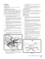
Page 25: ... position Repeat the above procedure to adjust the other control 3 lever into the same position Adjust so that both levers are even with each other when in the neutral position Leveling the Mower Deck When correctly adjusted the mower deck should be level side to side and the front of the deck should be approximately 1 4 lower than the rear of deck NOTE Check the tractor s tire pressure before per...

Page 26: ... the 8 inner hex nuts with a wrench and tighten the outer hex nuts against the inner hex nuts to lock them in the adjusted position Adjusting the Gauge Wheels 8 3 Keep hands and feet away from the discharge opening of the cutting deck NOTE The deck gauge wheels are an anti scalp feature of the deck and are not designed to support the weight of the cutting deck The mower deck cutting height can be ...

Page 27: ...ove the rollers 2 as the shaft is fully withdrawn from the right rear roller bracket See Fig 6 8 Insert the roller shaft through the other roller bracket hole 3 Slide the rollers onto the shaft as you slide the shaft to the left If necessary rotate the roller shaft to align the flat area on 4 the left end of the shaft with the flat of the hole in the left roller bracket Slide the shaft through the...

Page 28: ...icing Electrical System A fuse is installed to protect the tractor s electrical system from damage caused by excessive amperage Always use the same capacity fuse for replacement If the electrical system does not function check for a blown fuse See Figure 7 3 If you have a recurring problem with blown fuses have the tractor s electrical system checked by your Service Dealer Relays and Switches Ther...

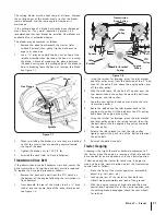
Page 29: ...des the most horizontal run of the belt between the deck idler pulleys and the PTO pulley on the bottom of the engine Sitting behind the tractor facing forward reach 2 beneath the tractor to grasp the belt at the front of the PTO pulley 8 3 Use caution to avoid pinching your fingers when rolling the belt off the PTO pulley Pull the left side of the belt rearward and downward 3 while manually turni...

Page 30: ... the idler 4 bracket movable pulley rearward against the spring tension and slide the backside of the belt onto the movable idler pulley Refer to Figure 7 3 Rolling the Belt onto the PTO Pulley Using the deck lift handle raise the deck to the 1 position that provides the most horizontal run of the belt between the deck idler pulleys and the PTO pulley on the bottom of the engine Make certain the b...

Page 31: ... leverage pivot the idler bracket 3 and idler pulley away from the backside of the V belt then lift the belt off and above the engine pulley and off the idler pulley With the belt loose lift the belt off up and over the 4 two transmission drive pulleys Remove the belt from the engine and idler pulleys Loop the new belt and slide over and onto the two 5 transmission pulleys Route the belt above the...

Page 32: ...e first three steps in the previous sub 2 section Tractor Creeping to verify that the tractor is not creeping If creeping adjust following the instructions in that sub section Recheck the tracking after making any adjustments to 3 the transmission control rods If uneven tracking persists note which direction the 4 tractor is tracking If the tractor tracks to the right adjust the a control lever st...

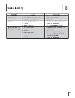
Page 33: ...ck adjustment 1 Sharpen or replace blade 2 Check tire pressure in all four tires 3 Mower will not mulch grass If Equipped w Mulching Kit Engine speed too low 1 Wet grass 2 Excessively high grass 3 Dull blade 4 Place throttle choke control lever in FAST 1 rabbit position Do not mulch when grass is wet 2 Mow once at a high cutting height then 3 mow again at desired height or make a narrower cutting ...

Page 34: ... Mulch Plug Kit 19A 115 100 Rear Bumper 19A 116 100 Rear Spreader 190 117 100 Sun Shade The following attachments and accessories are compatible with your RZT tractor See your authorized dealer or the retailer from which you purchased your tractor for information regarding price and availability Attachments Accessories 9 ...

Page 35: ...Notes ...
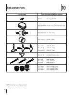
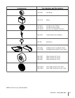
Page 36: ...0 22 S1 Fuel Filter Kohler KH 12 050 01 S Oil Filter Kohler 954 04137A V Belt 42 Deck 954 04044A V Belt 50 Deck 954 040138A V Belt 54 Deck 954 04043A Drive Belt Transmissions 942 04308 Blade 42 Deck 942 04053C Blade 50 Deck 942 0677B Blade 54 Deck 918 04822A Deck Spindle 42 Deck 918 04125B Deck Spindle 50 Deck 918 04608A Deck Spindle 54 Deck Replacement Parts 10 36 ...

Page 37: ...s Cap 2 25 sealed EPA III Carb 946 04539 Throttle Choke Control Kohler 925 1745 Ignition Key 631 04344 Discharge Chute Assembly 42 Deck 631 04092B Discharge Chute Assembly 50 54 Deck 634 04293 Wheel Assembly 42 Deck 634 04128 Wheel Assembly 50 Deck 634 04295 Wheel Assembly 54 Deck 634 04237B Caster Wheel Assembly 42 Deck 634 04321A Caster Wheel Assembly 50 54 Deck 37 SECTION 10 REPLACEMENT PARTS ...

Page 38: ...stments clutch adjustments deck adjustments and normal deterioration of the exterior finish due to use or exposure d Service completed by someone other than an authorized service dealer e MTD does not extend any warranty for products sold or exported outside of Canada including possessions and territories f Replacement parts that are not genuine MTD parts g Transportation charges and service calls...

Page 39: ...E RESPECTIVE MANUFACTURERS SERVICE DEALERS Belts light bulbs clutch parts friction wheels grass bags tires seats rider deck wheels and cutting blades are covered by a 60 day limited warranty Batteries are warranted against defect for 90 days at 100 of their value and 50 of their value for the period between the 91st day and the 120th day Fuses shear bolts and blade adapters are considered consumab...

Page 40: ...ays If you have a question regarding your warranty coverage you should contact the MTD Consumer Group Inc Service Department In the U S A MTD LLC at P O Box 361131 Cleveland Ohio 44136 0019 or call 1 800 800 7310 or 1 330 220 4683 or log on to our Web site at www mtdproducts com In Canada MTD Products Limited Kitchener ON N2G 4J1 or call 1 800 668 1238 or log on to our Web site at www mtdcanada co...

Page 41: ...nty coverage may be excluded from such warranty coverage if MTD Consumer Group Inc demonstrates that the outdoor equipment engine has been abused neglected or improperly maintained and that such abuse neglect or improper maintenance was the direct cause of the need for repair or replacement of the part That notwithstanding any adjustment of a component that has a factory installed and properly ope...

Reviews: