background image

P4 

Owner’s Manual 2015 

Charge completion is when the 100% Green LED is lit (Fig. 4.6A No. 5). The remote LED will be green. 
 
Repeated  “Short  Charging”  leaving  the  charge  short  of  100%  will  shorten  operating  cycle  distance  and 
reduced battery life.  
 
A  Green  LED  continuously  lit  indicates  the  batteries  are  completely  charged.  The  Charger  may  now  be 
unplugged from the AC source. If the batteries will not be used for a length of time, check monthly for the 
charge level. It is also acceptable to leave the Charger plugged in. The Delta-Q has the capability to test 
and recharge if necessary. 
 
A  fault  occurring  while  charging  causes  the  RED  FAULT  LED  and  the  remote  LED  to flash  with  a  code 
relaying  the  error.  Some  errors  may  require  repair  by  a  qualified  technician  and  others  may  be  simply 
transient and  will  automatically recover  when the fault condition is eliminated and the Delta-Q cycled  by 
disconnecting the AC source for a minimum of 11 seconds.  
 

NOTICE:

 A Yellow (Amber) flashing LED in the upper Bar Graph (Fig. 4.6A No. 3) and a flashing 

yellow  remote  LED  indicates  the  thermostatic  control  has  limited  the  Charger  output  due  to 
ambient temperature conditions. It is still charging, but at a reduced rate. 


4.6.2   RED LIGHT CHARGER ERROR CODES 


1 FLASH

 = Battery Voltage High: Auto-recover. May be temporary condition, or wrong Charger installed, 

i.e. 36 volt Charger on 48 volt battery pack. 
 

2 FLASH

 = Battery Voltage Low: Auto-recover. Confirm each individual batteries minimum voltage with a 

voltmeter.  Two  or  more  6  volt  batteries  register  less  than  5.85  volts,  or  accumulative  total  pack  voltage 
has  been  discharged  to  less  than  20%  remaining.  Vehicle  operation  will  cease  until  batteries  are 
recharged. See EXCESSIVELY DISCHARGED BATTERIES Section 4.6. 
 

3  FLASH

  =  Charge  Timeout:  The  charging  did  not  complete  in  allowed  time,  12-14  hours.  This  may 

indicate  a  battery  problem,  or  that  the  Charger  output  was  reduced  due  to  high  ambient  temperatures. 
Disconnect AC supply, confirm sufficient ventilation, allow cool down time, and restart Charger. 
 

NOTICE:


If the Delta-Q is exhibiting a 3 flash fault and it has been determined that the cause was not 

due to ventilation or high ambient temperature, the following procedure may restore the battery pack to 
normal operation. 


Battery posts and terminals must be clean and free of corrosion. 


Check that electrolyte level just covers plates. 


Plug in charger for at least a 16 hour charge. 


Check and fill electrolyte. 


Drive the vehicle for less than half the distance normally driven. 


Repeat the above steps until the Delta-Q goes green 100% charge on a 16 hour charge. 

If repeated cycles (5-7) do not result in a 100% green charge, the batteries are beyond useful life and 
will need replacement.


4  FLASH

  =  Check  Battery:  The  batteries  could  not  be  trickle  charged  up  to  a  minimum  level  to  start 

Charger.  This  may  be  the  result  of  badly  discharged  batteries,  or  one  (or  more)  damaged  cells.  See 
EXCESSIVELY DISCHARGED BATTERIES Section 4.6. 
 

5  FLASH

  =


Over-Temperature:  The  Charger  shutdown  due  to  high  internal  temperature.  May  require 

reset (AC unplugged) and cool down to restart charging cycle. This fault may indicate inadequate cooling 
airflow or high ambient air temperatures. Check for debris or blockage at cooling fins. Move the vehicle to 
a cooler, well ventilated area, or adjust time of day when charging. 
 

6  FLASH

  =  Delta-Q  Charger  Fault:  A  fault  was  detected  either  in  the  batteries  or  in  the  Charger.  The 

batteries must be tested to ensure there is no damage to one or more cells. If the batteries are found to 
be good, the Charger may need to be replaced by a qualified technician.  

 
A  STEADY  RED  FAULT  LED 

confirms  an  internal  electrical  fault  of  the  Delta-Q  and  requires  Charger 

replacement and return. 


4-5 

Summary of Contents for EAGLE P4

Page 1: ...Owner and Operator Manual EAGLE P4 Electric Vehicles P N 712081 05 2015 ...

Page 2: ...of the National Highway Traffic Safety Administration NHTSA as stated in the Code of Federal Regulations Title 49 Part 571 Standard 500 Low Speed Vehicles To the best knowledge of Columbia ParCar Corp the material contained herein is accurate as of the date this publication was approved for printing Columbia ParCar Corp is not liable for errors in this manual or for incidental or consequential dam...

Page 3: ...OR PEDAL 3 3 10 HOUR METER INDICATOR 3 3 11 STEERING WHEEL 3 3 12 CHARGER RECEPTACLE 3 3 13 TURN SIGNAL HAZARD WARNING SWITCH 3 3 14 HORN BUTTON 3 3 15 CAB HEATER 3 4 MAINTENANCE ACCESS 3 5 DRIVING THE VEHICLE 3 6 PRE OPERATION CHECKLIST 4 0 ELECTRIC SYSTEM 4 1 IMPORTANT INFORMATION 4 2 BATTERY INSPECTION MAINTENANCE 4 3 BATTERY CLEANING 4 4 CONDITIONS WHICH AFFECT CHARGING 4 5 BATTERY CHARGERS 4 ...

Page 4: ...2 TRANSPORTING YOUR VEHICLE 7 0 VEHICLE STORAGE 7 1 BATTERY PREPARATION 7 2 VEHICLE PREPARATION 7 3 RETURNING VEHICLE TO SERVICE NOTICE In an effort to streamline product support please ensure your vehicle is properly registered with Columbia ParCar Registration allows for more effective product support including product updates and warranty processing Please consult with your servicing dealer to ...

Page 5: ...s situation which if not avoided will result in death or serious injury Warning indicates a hazardous situation which if not avoided could result in death or serious injury Caution indicates a hazardous situation which if not avoided could result in minor or moderate injury NOTICE Notices are messages not related to personal injury They will provide key information to prevent property damage and t...

Page 6: ... ACEplus F Sep Ex Regen w encoder ACEplus Digit 5 Voltage Batteries 3 36 Volt 4 48 Volt 8 6 Volt B 48 Volt 4 12 Volt G 48 Volt Gel 8 6 Volt Digit 6 Standard or Special Product Standard Product Special Product Digit 7 Controller Amperage 3 300 Amp 4 400 Amp 5 500 Amp Digit 8 Axle Brake System Z H12 Rear Mechanical Y H12 Rear Hydraulic X H12 Front Rear Hydraulic Digit 9 Year Built L 2012 M 2013 N 20...

Page 7: ... Length 96 in Overall Width 45 in Overall Height 51 in Horsepower 15 3 HP 1750 rpm 17 3 HP 1750 rpm Brakes Auto adjusting dual mechanical rear drum parking brake automatically releases TIRES RECOMMENDED PSI 215 60 8 18 5 x 8 5 8 non marking 205 50 10 480 12 165 65R13 215 50R13 175 70R13 22 25 psi 22 25 psi 30 psi 32 psi 32 psi 32 psi 32 psi DRIVE RATIO LE 12 44 1 SE 10 35 1 1 3 ...

Page 8: ...e the designer the manufacturer and the safety engineer can help minimize the possibility of an accident their combined efforts can be erased by a single careless act 2 2 SAFETY GUIDELINES Observe the following guidelines for safe operation Define where vehicles may be driven Define who should be allowed to drive the vehicle Instruct first time drivers Maintain vehicles in a safe driving condition...

Page 9: ...e by authorized persons Never exceed the capacity ratings of the vehicle Exceeding these limits may endanger occupants Personal injury may result if body parts arms head and legs are not kept inside vehicle while moving Do not start moving until all occupants are seated Remain seated and hold on while vehicle is in motion Before leaving your seat completely stop vehicle and lock parking brake If v...

Page 10: ...during storage 3 2 INSPECTING THE VEHICLE After battery charging perform a pre delivery inspection of the vehicle Also before using the vehicle there are checks that must be performed to ensure that it is in safe proper working order NOTICE Vehicle should be inspected immediately after delivery Use the following guidelines to make sure there are no obvious problems Examine the contents of all pack...

Page 11: ...g the power draw when vehicle is not in use Turning the power keyswitch to OFF is highly recommended whenever vehicle is not in use Always take the key out of the keyswitch when leaving the vehicle 3 3 2 DIRECTION SELECTOR Figure 3 3 1 Arrow B When the direction selector is in the vertical position the vehicle s direction signal is turned OFF or in neutral Turn direction selector to the right from...

Page 12: ...re operating the vehicle Promptly replace if removed or damaged Contact Columbia ParCar for replacements if needed 3 3 7 SYSTEM STATUS LIGHT Figure 3 3 1 Arrow H Some vehicle will be equipped with an additional green System Status LED light located on the dash With the power keyswitch in the ON position the controller is powered up and this light should display a steady green light If this green s...

Page 13: ...uld always be kept at a minimum 3 3 10 HOUR METER INDICATOR NOT SHOWN If equipped the hour meter indicates the total number of hours the vehicle has been operating It would be located immediately below the Battery State of Charge meter 3 3 11 STEERING WHEEL The steering wheel controls the path of the vehicle exactly the same as a conventional automobile wheel 3 3 12 CHARGER RECEPTACLE REMOTE LED T...

Page 14: ...the switch to the UP position To activate the fan only place the switch in the DOWN position NOTICE If the toggle switch is in the Fan Heat position and no heat is occurring a circuit reset is required On a side panel there is a 3 8 hole Inside is a reset tab Using a non conductive device push the tab to reset the circuit 3 4 MAINTENANCE ACCESS For vehicles with bench seats to gain access for serv...

Page 15: ...d connections are tight Tire Pressure Inflated to recommendation per Section 1 4 Do not exceed maximum stated on tire sidewall Lights Horn and Reverse Buzzer Head tail and brake lights illuminate Press horn button to sound horn Reverse buzzer sounds Brakes Brake pedal has firm pedal pressure with minimal travel Parking brake has proper engagement and release Steering Responsiveness and the absence...

Page 16: ...onnect battery pack before servicing or repairing the vehicle See Section 2 4 Always wear full face shield when working on or near batteries All batteries used in electric vehicles can explode Batteries produce explosive hydrogen gas at all times especially during charging or discharging Ventilate area when charging batteries Do not attempt to charge a battery if it is frozen or if the case is bul...

Page 17: ...r corroded battery terminals should be replaced or cleaned as necessary Failure to do so may cause overheating during operation Do not attempt to recharge batteries with a charger not designed for your vehicle Only trained technicians should service the Delta Q charger Contact your Columbia Dealer for assistance 4 2 BATTERY INSPECTION MAINTENANCE Check the electrolyte level on new batteries before...

Page 18: ...ge dirt and other debris Do not hose wash electronic controllers switches solenoids and other electrical control devices Cover as necessary to prevent splashing Clean battery terminal connections with baking soda sodium bicarbonate and water solution Mix 5 teaspoons baking soda per quart of water Use a stiff bristle brush rinse with clean water and dry with a clean cloth Do not allow solution to e...

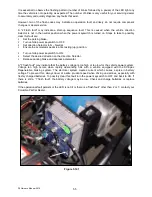
Page 19: ...test All Delta Q LED s will flash in sequence and then a trickle current will be applied to batteries until a minimum voltage is reached In Figure 4 6A No 3 indicates the Bar Graph and No 2 indicates the lowest LED Three 3 amperes is displayed as the lowest LED on the Bar Graph If the batteries meet the minimum voltage requirements of the Charger signifying they are serviceable chargeable the Char...

Page 20: ...eout The charging did not complete in allowed time 12 14 hours This may indicate a battery problem or that the Charger output was reduced due to high ambient temperatures Disconnect AC supply confirm sufficient ventilation allow cool down time and restart Charger NOTICE If the Delta Q is exhibiting a 3 flash fault and it has been determined that the cause was not due to ventilation or high ambient...

Page 21: ... number of blinks for the first digit followed by a short pause then the number of blinks for the second digit followed by a longer pause To check change the charging algorithm Disconnect the charger positive connector from battery pack Apply AC power and after the LED test the algorithm will be displayed for 11 seconds To change the algorithm touch the positive connector during the 11 second disp...

Page 22: ...te longer battery life NOTICE During this process the LEDs will go through their normal routine Red LEDs counting up for of charge along with the illuminated Red LED Battery Type and then the Green LED and Red Battery Type LED will blink until the unit returns to the maintenance mode and a steady Green LED and steady Red Battery Type LED Not applicable to Gel Profile 4 7 1 TROUBLESHOOTING PROBLEM ...

Page 23: ... that a possible battery problem exists and that the charge cycle has been terminated at this point Please call ParCar technical support for further assistance NOTICE Disconnecting and reconnecting the AC power supply cord will reset the charger 4 8 EXCESSIVELY DISCHARGED BATTERIES NOTICE Columbia Dealer will have the equipment and experience to perform the following battery inspections The charge...

Page 24: ...e is not in use for 3 5 or more days is encouraged Recharge batteries as soon as they become 20 or more discharged less than 1 238 sp gr Make it a regular habit to plug in the charger when the vehicle is not in use Batteries may be recharged if vehicle has been driven 15 minutes or more since the previous charge Make sure your electrical outlet is operational Never go below 20 state of charge or 8...

Page 25: ...ry pack consists of a fill tube one end having a filter screen the other having a female coupler and a rubber squeeze bulb Check the battery pack water level weekly by Inserting the fill tube filter end in an approved water supply Attaching the female coupler to the battery pack male coupler Squeeze the rubber ball until firm which indicates that filling is complete Immediately disconnect the coup...

Page 26: ...4 pedal free travel before resistance is felt Maximum pedal free travel should not exceed 2 measured from floor board to top of pedal See Figure 5 5 1 The parking brake is applied by depressing the parking brake pad at the top of the brake pedal which locks the brakes in place If the brakes fail to hold the vehicle in position contact your Columbia Dealer for qualified service assistance 5 3 HYDRA...

Page 27: ...ck lug nut torque with the vehicle on the ground NOTICE The wheel may be bent if not torqued in a crossing pattern This will cause the wheel to wobble 5 7 CLEANING Wash underside to remove all dirt and debris Do not direct high pressure water at the controller speed switches or tops of the batteries Wash body and seat with a mild detergent Do not use abrasives bodies are painted Frequent washings ...

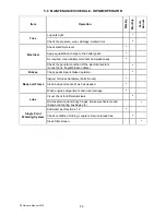
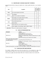
Page 28: ... the general condition of the electrical system connections frayed broken cables Brakes Check pedal park brake operation Body and Frame Inspect for loose hardware bolts nuts Clean body and seats Wash as needed Wash engine compartment and undercarriage Lube Visual check for differential leak Oil movement points body hinges brake mechanisms and linkage leaf spring bushings etc Single Point Watering ...

Page 29: ...direction Keyswitch for loose wires or faulty switch Batteries for loose terminals corrosion electrolyte level or state of charge Motor for loose wires open circuits or worn brushes Will not move with power keyswitch is on and the direction Selector is in the desired direction Controller green light See Section 5 12 Runs slow Batteries for loose terminals corrosion electrolyte level or state of ch...

Page 30: ...elerator pedal is at its resting up position Turn vehicle power keyswitch to ON Select the desired direction on the direction Selector Release parking brake and depress accelerator A 7 flash fault may indicate that the battery voltage is too high or too low for the vehicle power system Voltage too high occurs when rapidly descending hills with a vehicle equipped with the ACEplus Regenerative braki...

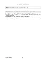
Page 31: ...nces or on the highway observe the following Use trailers specifically designed to carry your Columbia ParCar vehicle that meets all federal state and local requirements Secure vehicle to the trailer following trailer manufacturer s instruction The key should be removed from the vehicle the parking brake firmly locked and the wheels blocked On vehicles equipped with high or wide additions or acces...

Page 32: ...isconnect the batteries See Section 2 4 Batteries in a low state of charge will freeze at higher temperatures than fully charged batteries Do not attempt to charge a battery that is frozen or if battery case is excessively bulged Properly dispose of battery because frozen batteries can explode Table B indicates freezing points of batteries at different specific gravities TABLE B SPECIFIC GRAVITY F...

Page 33: ...maintenance per Section 3 6 For vehicles with a single point watering system After the batteries have been fully charged connect the system to its water supply for 3 5 seconds then disconnect regardless of whether or not the batteries are completely full Return the vehicle to its regular service Place the vehicle back into its regular watering schedule waiting at least 1 week until next watering 7...

Page 34: ...P4 Owner s Manual 2015 1115 Commercial Avenue Reedsburg WI 53959 Phone 608 524 8888 800 222 4653 Web www parcar com ...

Reviews: