P4
Owner’s Manual 2015
3.3.3 LIGHT SWITCH
– Figure 3.3.1 - Arrow C
Move switch up to activate headlights and taillights, down to turn off.
3.3.4 AUXILIARY EQUIPMENT SWITCH - Figure 3.3.1 Arrow D
A switch for auxiliary equipment will be located in this position.
3.3.5 BATTERY STATE OF CHARGE METER
– Figure 3.3.1 Arrow E
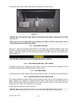
This meter will display the battery state of charge. As shown, it is an analog gauge meter with an
indicating needle and a colored background. It is a continuously reading meter. At rest with fully charged
batteries the meter should read in the right white region.
When accelerating quickly, the needle will move to the left green region near the very far left red region.
This is normal. If the needle continues past the green region into the very far left red region, it indicates
that the batteries are 80% discharged or basically empty (only 20% charge remaining). Recharge as soon
as possible to avoid a shut-down of the vehicle.
When decreasing speed, the needle will move to the right as electrical energy is being “regenerated” back
into the batteries.
NOTICE:
At 80% discharge, you must immediately charge batteries or vehicle operation will
cease and permanent battery damage could occur.
3.3.6 WARNINGS & OPERATING INSTRUCTION
– Figure 3.3.1
Arrow F & G
Read this information carefully before operating the vehicle. Promptly replace if removed or damaged.
Contact Columbia ParCar for replacements if needed.
3.3.7 SYSTEM STATUS LIGHT
– Figure 3.3.1 Arrow H
Some vehicle will be equipped with an additional green System Status LED light located on the dash.
With the power keyswitch in the “ON” position, the controller is powered up and this light should display a
steady green light. If this green status light is not lit or is flashing refer to Section 5.12 CONTROLLER
TROUBLESHOOTING.
3.3.8 BRAKE PEDAL/PARKING BRAKE
For vehicles with mechanical brakes Figure 3.3.1 shows the brake pedal (Arrow J) and the parking brake
lock (Arrow I). The parking brake lock (Arrow I) is a bar located at the top of the brake pedal. To lock foot
brake for parking, depress pedal and bar at the same time. Always apply parking brake when leaving the
vehicle. It remains applied until automatically released by depressing the accelerator pedal. Parking brake
can also be released by momentarily depressing the brake pedal, and then releasing it.
Figure 3.3.3 shows the brake pedal (Arrow L) and parking brake (Arrow N) for vehicles with hydraulic
brakes. These vehicles will have a hand parking brake located either on the floor as shown in Figure 3.3.3
or if equipped with bucket seats, located between the seats. To lock the brake, pull the brake lever
upward. To release, depress the button at the end of the handle and let the handle down to the original
position. Always apply parking brake when leaving the vehicle.
3-3


