


25
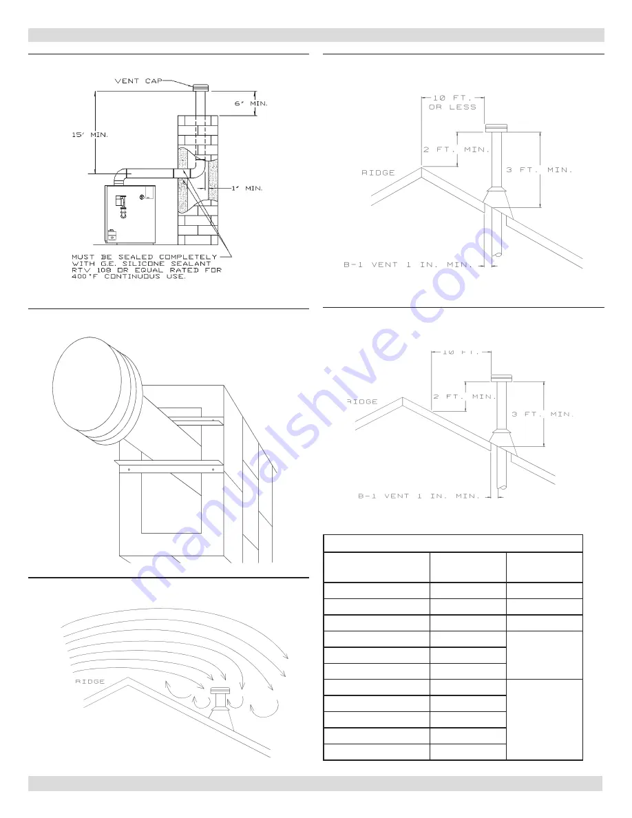
VERTICAL VENT PIPE INSTALLATION INSTRUCTIONS
Figure 17 - Vent Liner
Figure 18 - Vent Liner Support In Masonry Chimney
Figure 19 - Avoid areas of Wind Currents
Figure 20 - Termination 10 ft (3m) Or Less From
Ridge
Figure 21 - Termination More Than 10 Ft (3m) From
Ridge
Table 4 Roof Pitch Chart
Roof Pitch
Height
Above Roof
Brace
Flat to 7/12
1.0 ft (0.3m)
Over 7/12 to 8/12
1.5 ft (0.5m)
Over 8/12 to 9/12
2.0 ft (0.6m)
Over 9/12 to 10/12
2.5 ft (0.8m)
Brace to Roof
at top
Over 10/12 to 11/12 3.3 ft (1.0m)
Over 11/12 to 12/12 4.0 ft (1.2m)
Over 12/12 to 14/12 5.0 ft (1.5m)
Brace to Roof
at Top and
Mid Point
Over 14/12 to 16/12 6.0 ft (1.8m)
Over 16/12 to 18/12 7.0 ft (2.1m)
Over 18/12 to 8/12
7.5 ft (2.3m)
Over 20/12 to 21/12 8.0 ft (2.4m)
Summary of Contents for CDVB-100
Page 15: ...15 HORIZONTAL VENT INSTALLATION INSTRUCTIONS Figure 9 Figure 7a Vent Cap Figure 7b Figure 8 ...
Page 22: ...22 HORIZONTAL VENT INSTALLATION INSTRUCTIONS Figure 16 Termination Clearances ...
Page 31: ...31 PILOT PILOT ELECTRICAL WIRING Figure 26 HOT WATER CONTROL AND INTERMITTENT IGNITION WIRING ...
Page 44: ...Columbia Company Main offices and factory Pottstown PA ...