background image


www.colmac.ie 

18 


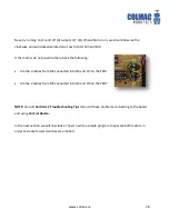
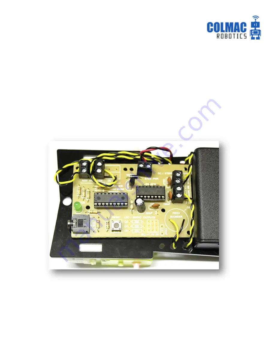
Route the cables through the remaining holes as shown and connect into the input terminals A0 

and A2 as shown on page 8. 


NOTE:

 Light Dependent Resistors (LDRs) do not have polarity (positive/negative) which means that 

it does not matter how the cables are connected into the terminal blocks. 


Finally, using the sticky pads, attach the E18 to the chassis in the position shown. 


A2 

A0 

Summary of Contents for Line Follower Robot Racing

Page 1: ...Line Follower Robot Racing Build Program Race...

Page 2: ...ade from acrylic sheet Two wheeled easily controlled differential drive and steering Significant distance between line sensors and wheels allowing the robot time to react and reduce the instances of o...

Page 3: ...nnecting the E18 Motor Control Board to your computer 23 5 Testing the E18 Motor Control Board 24 6 Driving the robot forward reverse 29 7 Turning the robot 32 8 Using the LDRs to detect a line 35 9 U...

Page 4: ...ircuit board PCB Some method of holding the GENIE E18 printed circuit board PCB while components are being soldered is very useful Some examples are shown below Assembly aids and small vices are ideal...

Page 5: ...f various inputs The outputs being controlled in this case are 2 x DC motors used to drive and steer the robot 1 x LED used to illuminate the line being followed The inputs used to control these outpu...

Page 6: ...board is shown below Fixed resistors have no polarity i e no positive or negative or and so can be inserted either way around Insert the resistors in their correct places either way around as they don...

Page 7: ...itors are used primarily to reduce electrical noise generated by the motors when they are running This electrical noise can interfere with the operation of the E18 microcontroller As such C3 and C4 ar...

Page 8: ...a positive and negative The negative leg is beside the grey band as shown below Step 4 Solder the transistor the reset switch and the USB jack The transistor operates as an automatic switch The USB j...

Page 9: ...rocontroller and L293D motor driver microchips should be inserted as shown The L293D chip allows the motor turn both clockwise and anti clockwise which gives forward reverse and turning motion in the...

Page 10: ...form Connections should not touch each other unless they are supposed to as circled below Step 7 Insert E18 and L293D microchips Try to handle the chip legs as little as possible but ensure that all l...

Page 11: ...m of insulation from the ends Shorten the legs of the LED as shown using snips pliers etc in order to minimise the chance of them touching each other and creating a short circuit Braid the individual...

Page 12: ...the legs of both LDRs as shown to approx 10mm using snips pliers etc in order to minimise the chance of them touching each other and creating a short circuit Braid the individual strands of the expose...

Page 13: ...wn and remove approx 5mm of insulation from the ends Solder the flying leads to the motors as shown Be careful with the motor connections as they are quite delicate If possible use similar colour cabl...

Page 14: ...d be attached to the plastic chassis using two sticky pads on each as shown below The motor cables are then fed through the holes as shown The edge of the motors should be positioned on the chassis as...

Page 15: ...hassis Attach 2 sticky pads to the battery pack on the switch side as shown Stick down the battery pack as seen below try to centre on the chassis in order to keep it balanced Feed the red V and black...

Page 16: ...case in order to accommodate the raised soldered joints and ensure secure fit to the chassis Then insert the cable from each motor into the M3 and M4 connectors preferably in the same manner as shown...

Page 17: ...lead through the centre cable hole Route the LED flying lead through the hole beside the PCB as shown Connect negative cable black in this case to the right side connection of output Q3 and the other...

Page 18: ...connected the wrong way around the E18 chip will heat up and may be damaged Step 14 Insert LDRs in chassis and connect to E18 PCB Insert the two LDRs into the front of the chassis as shown and feed t...

Page 19: ...ut terminals A0 and A2 as shown on page 8 NOTE Light Dependent Resistors LDRs do not have polarity positive negative which means that it does not matter how the cables are connected into the terminal...

Page 20: ...er bands are used to increase the grip of the wheels When attached the wheels should push fit on to the motor drive shaft Step 16 Assemble the rear spoiler and attach to chassis The 5mm end of the sup...

Page 21: ...www colmac ie 20 Congratulations you have built the COLMAC Line Follower Racing Robot...

Page 22: ...rom its developers at their website http www genieonline com Complete the required details in the online form accessed through the Downloads tab and a link will be emailed to you click on the link to...

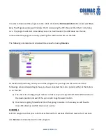
Page 23: ...ogramming Editor To open GENIE Programming Editor click the GENIE Programming Editor icon on the desktop or use the start menu to locate the program Menu Bar Programming Area Tool Bar Programming Comm...

Page 24: ...r computer to the GENIE microcontroller The cable can be used with all GENIE microcontrollers and can be purchased from http colmac ie product download cable Connect the GENIE USB Plug Play cable and...

Page 25: ...u are using Select Microcontroller from the tool bar followed by Program Settings Select the GENIE E18 chip NOTE This must be done each time a new program is written unless E18 is set as default The P...

Page 26: ...are Pin 17 connected to A D0 on PCB o Input A1 and D1 share Pin 18 connected to A D1 on PCB o Input A2 and D2 share Pin 1 connected to A D2 on PCB We are only using A D0 and A D2 for this line followe...

Page 27: ...n status LED should flash and the software should indicate that the microcontroller is now connected as shown We can now test that both motors and the line illumination LED are working We will use the...

Page 28: ...te check the following Is the LED cable connected into the PCB with correct polarity as shown below Is the LED cable connected to the LED with correct polarity i e leg on flat side of LED connected in...

Page 29: ...ck the following Are the 2 cables from M4 connected into Q6 and Q7 on the PCB Are the 2 cables from M3 connected into Q4 and Q5 on the PCB NOTE Consult Section 12 Troubleshooting Tips if you still hav...

Page 30: ...r command is located under the Input and Output section of the flowchart symbols The Wait and Stop commands are located under the Program Control section of the flowchart symbols Commands will automat...

Page 31: ...ding how you have connected each motor polarity you may find that you need to set the sliders in the down position or one slider up and the other down in order to achieve forward motion when you downl...

Page 32: ...As mentioned previously when you run this program live you may now discover one of the following scenarios depending on how you have connected the motor polarity either at the motors or on the PCB a...

Page 33: ...ile it is moving is based simply on turning off one motor and leaving the other running Construct and edit the following flowchart as shown Settings for motor control are shown You will see these outp...

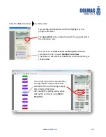
Page 34: ...ation runs Now click on the View several monitor panels at once command in order to open Multiple Panel View This allows us see what each flowchart command is doing as shown below To turn left motor M...

Page 35: ...rn is ask your teacher to explain Points to consider It is not possible to control the number of revolutions of a DC motor as it is with a servo or stepper motor Controlling the amount your robot turn...

Page 36: ...ss The GENIE software takes whatever analogue resistance value the LDR has at any given moment and converts it into a digital reading of between 0 and 255 A digital value of 0 corresponds to an LDR re...

Page 37: ...reate the loop firstly left click and hold the mouse over the right connection point on the Outputs symbol Drag the connecting line to the right and then upwards to create the first 90 bend To create...

Page 38: ...facility allows you watch your program animate as it runs live on the microcontroller By clicking on View several monitor panels at once as shown below we can now observe what the LDRs are reading al...

Page 39: ...www colmac ie 38...

Page 40: ...ote of both readings as shown below Readings on white area A0 224 A2 231 NOTE Depending on number of batteries used and ambient lighting conditions etc your readings may be significantly different Ind...

Page 41: ...231 on the white surface LDRs read a max of approx 184 on the black line For the purposes of this line follower we can summarise by saying that once the LDR readings go above 190 then they have defini...

Page 42: ...s and No if necessary We will now edit this flowchart so that it carries out the following program 1 Turn on the line illumination LED connected to Q3 2 Check if the LDR readings are more than 190 190...

Page 43: ...use the robot to veer off line Tick the and box to open the second expression This instructs the program to compare both readings from A0 and A1 to see if they are more than 190 If they are then the r...

Page 44: ...c ie and measures approx 2400mm x 1200mm You can create your own track with a roll of standard 20mm wide black insulating tape and using it to create a track on a lighter coloured floor Don t make the...

Page 45: ...off the line to the right and motor M3 is turned off in order to turn the robot left and back to the line In the third Compare command if A2 reads more than 190 then the robot has moved off the line t...

Page 46: ...program it to stop and look for the line if it loses it completely This can be accomplished by instructing the robot to firstly stop then look left and if it does not find the line there to then look...

Page 47: ...mand that will check if both LDRs A0 and A2 have lost sight of the black line i e if the LDR reading has gone above 190 We will now look in closer detail at the commands that follow this new Compare c...

Page 48: ...robot to perform a two wheeled left turn in order to look for the line Note that the sliders are set slightly less than max in order to slow the rotation speed The Compare command checks to see if A2...

Page 49: ...f these other commands can be found in the Help section of the software by clicking on GENIE Programming Editor Help as shown below Then select Flowchart commands as shown This will open a window disp...

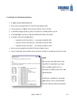
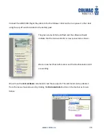
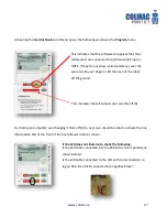
Page 50: ...ng the Troubleshoot GENIE tool in the Help section Follow the steps in the window that opens Test the supply voltage across pins 5 and 14 of the E18 microchip These are the power connections There sho...

Page 51: ...sses o You didn t apply enough solder or the pad wasn t hot enough to accept the solder The lead is loose in the hole or the solder isn t firmly attached to the pad o You possibly moved the lead befor...

Page 52: ...s Sometimes a pad can break off either during initial soldering or later de soldering If this happens scrape off the green protective coating and reconnect the broken track using cable links soldered...

Page 53: ...the PCB with 2 x 100nF ceramic capacitors attached across terminals Q4 Q5 and Q6 Q7 as shown below In the event that you still experience these types of issues you can solder a further 100nF capacito...

Page 54: ...www colmac ie 53 Circuit and PCB diagrams courtesy of www genieonline com...

Page 55: ...ltage supply to the board The manufacturers indicate that up to a 12V battery supply may be used but recommend not to use a 9V PP3 battery Again this will necessitate recalibration and editing of wait...

Reviews: