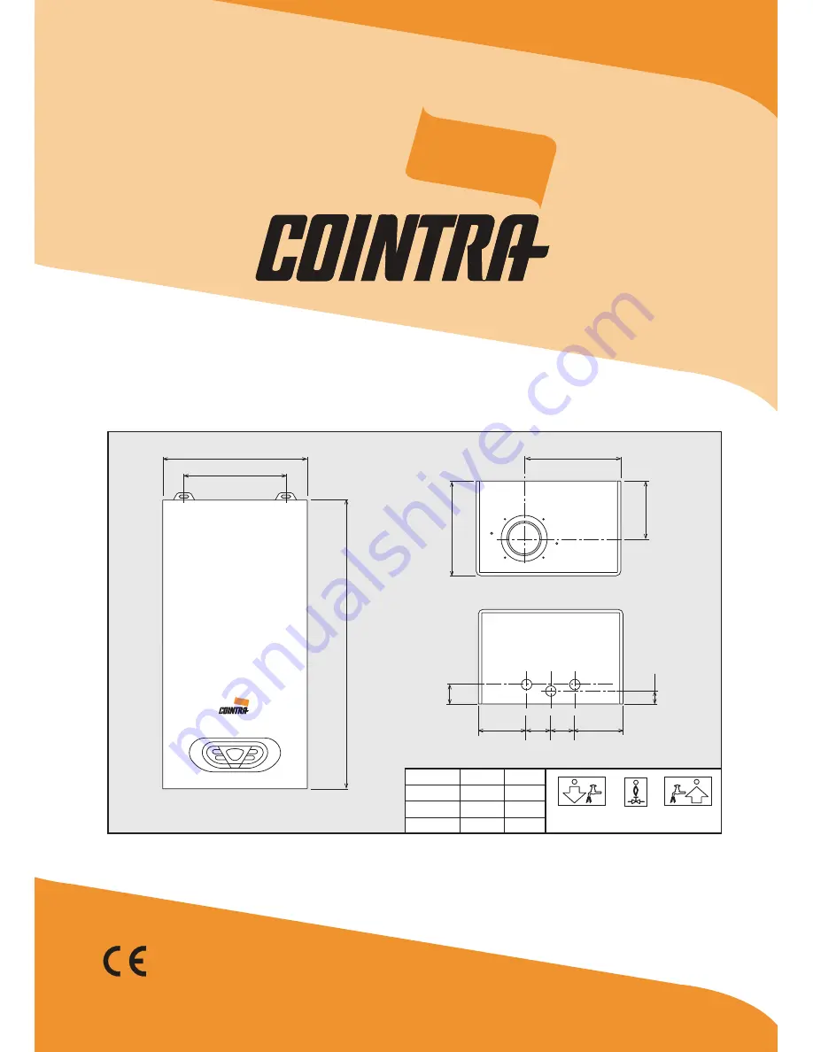
SUPREME E TS
195
200
11
8
40
50 50
=
27
C
B
D
E
Modello
11 E TS14 E TS17 E TS
A mm
295335375
A
595
E mm
210250290
N
- INSTRUC
TIONS FOR USE, INSTALLATION AND MAINTENANCE
Page 1: ...SUPREME E TS 195 200 118 40 50 50 27 C B D E Modello 11 E TS 14 E TS 17 E TS A mm 295 335 375 C D B A 595 E mm 210 250 290 EN INSTRUCTIONS FOR USE INSTALLATION AND MAINTENANCE ...
Page 2: ...ing operation During a DHW demand generated by drawing domestic hot water the display detail 11 fig 1 shows the actual DHW outlet temperature Fault In case of a fault see cap 4 4 the display detail 11 fig 1 shows the fault code and during safety standby times the messages d3 and d4 2 3 Lighting and turning off Connection to the power supply During the first 5 seconds the display shows the card sof...
Page 3: ...with all the Cny flue configurations given on the dataplate Some configurations may be expressly limited or not permitted by law standards or local reg ulations Before installation check and carefully follow the instructions Also comply with the instructions on the positioning of wall and or roof terminals and the minimum distanc es from windows walls ventilation openings etc Baffles Unit operatio...
Page 4: ... and maximum which must be those given in the technical data table according to the type of gas Connect a suitable pressure gauge to the pressure point B downstream of the gas valve Activate the TEST mode see cap 4 1 Press the off button for 2 seconds to access the gas valve Calibration mode The card goes to the setting q02 displaying the actually saved value by pressing the DHW buttons If the pre...
Page 5: ...ult code Fault Possible cause Cure A01 No burner ignition No gas Check the regular gas flow to the water heater and that the air has been eliminated from the pipes Ignition detection electrode fault Check the wiring of the electrode and that it is correctly positioned and free of any deposits Faulty gas valve Check gas valve and replace it if necessary Gas valve wiring disconnected Check the wirin...
Page 6: ...tput kW 19 2 23 9 29 2 Min heat output kW 7 1 8 8 10 7 Pmax efficiency 88 5 88 7 88 9 Burner nozzles G20 no x Ø 10 x 1 25 12 x 1 25 14 x 1 25 Gas supply pressure G20 mbar 20 0 20 0 20 0 Max gas pressure at burner mbar 13 0 13 0 15 0 Min gas pressure at burner mbar 2 0 2 0 2 0 Max gas delivery G20 m3 h 2 30 2 85 3 48 Min gas delivery G20 m3 h 0 88 1 10 1 33 Burner nozzles G31 no x Ø 10 x 0 77 12 x ...
Page 7: ...5 4 Wiring diagram fig 15 Electrical circuit 81 1kW L N 230V 50 Hz 16 N L ABM02 73 R1 R2 R3 R4 288 T T 344 4 3 2 1 44 38 SUPREME E TS 7 EN ...
Page 8: ... p A Address Via Ritonda 78 a 37047 San Bonifacio VR Italy declares that this unit complies with the following EU directives Gas Appliance Directive 2009 142 Low Voltage Directive 73 23 amended by 93 68 Electromagnetic Compatibility Directive 89 336 amended by 93 68 President and Legal Representative Cav del Lavoro Dante Ferroli ...