Connect the Inputs and Outputs (Optional)
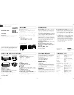
The vision system’s I/O connector supplies connections for the acquisition trigger and high-speed outputs.
CAUTION
:
All cable connectors are keyed to fit the connectors on the vision system. Do not force the connections
or damage may occur.
Note
:
l
I/O wiring or adjustments to I/O devices should be performed when the vision system is not receiving power.
l
The vision system must be Online for the discrete inputs and outputs to function.
l
Refer to the
In-Sight
®
Explorer Help
file for details on configuring the discrete input and output lines.
Option 1: Connect the Breakout Cable
Note
: You can clip unused wires short or use a tie made of non-conductive material to tie them back.
1. Connect the Breakout cable’s M8 connector to the vision system's I/O connector.
2. Connect the trigger and high-speed I/O wires to an appropriate device (for example, a PLC, trigger sensor or
strobe light). For more information, refer to
12
Installation


