background image

9

3. Adjust gap by adjusting the 3 locknuts “F” and checking with

a feeler gauge to be sure gap is the same on both ends of
the solenoid.

4. Adjustment is now complete and the brake properly set.

Replace the electrical cover, reconnect the power supply,
and check lifting motor brake action.

WIRING

Refer to Figures 7A, 7B and 7C.

Single-phase units (115/230V) are wired for 230V and
230/460V-3 phase units are wired for 230V unless otherwise
specified when ordering. Lifting motors ordered with other 
3-phase voltages are single-voltage only. Conversion of dual
voltage units can be done simply and quickly as follows.

1. DISCONNECT LIFTING MOTOR FROM POWER SUPPLY

and remove electrical cover.

2. On 230/460V-3 phase units converting to 460V requires

removing the C1, C2 and C3 jumpers as shown on the
wiring diagram 983CE2100-000. The motor leads T4, T5 and
T6 are then connected to the blocks as shown. Save the
three jumper wires for conversions back to 230V. One of the
transformer leads H2 (230V) and H4 (460V) is connected to
the contactor as shown depending on the voltage.

On 115/230V-1 phase units, connections are only modified
at the terminal blocks as shown on wiring diagram
981CE0100-000.

3. Make sure that all of the screw clamps on the contactor and

terminal blocks are tightened. Tug on the wires to ensure
they are securely connected.

4. Check the operation of the lifting motor, ensuring that the

direction of travel is correct (See INSTALLING LIFTING
MOTOR, page 5).

IMPORTANT: Always refer to the wiring diagram located on the
inside of the electrical cover or Figures 7A, 7B and 7C when
performing electrical repairs. Make sure all terminals are securely
fastened and check for damaged insulation. It is also imperative
that the power circuit has conductors of adequate size.

LUBRICATION

Refer to Figure 9.

Proper lubrication is necessary to ensure a long and reliable
lifting motor life. Refer to the following and the
RECOMMENDED LUBRICATION SCHEDULE for lubrication
points, type of lubricant, and frequency of lubrication.

Load Chain

Clean the load chain with acid-free solvent and coat with new
SAE 90 gear oil. Wipe excess oil to prevent dripping. Never
apply grease to the chain.

Gearing

The gearbox of this lifting motor is filled at assembly with 1½
pints of SAE 90 EP gear oil. To check oil level, hang the unit by
the suspension hook (the unit and decals will be upside down)
and remove the oil level check plug. With the lifting motor
hanging level, the gear oil should be even with the hole.

Bearings

All bearings except hook and idler sheave bearings are
lubricated at the factory and should not require additional
lubrication. Noisy or worn bearings should be replaced.

Limit Switch Shaft

Remove any dirt accumulation and spray with a general
purpose lubricant.

Hook Bearing

Apply a few drops of new SAE 30 gear or motor oil around the
edge of the bearing.

Idler Sheave Bearing (Bushing)

Disassemble load block and apply a light coat of NLGI #2
grease, or equivalent, inside of bearing.

NOTE: If lifting motor is used in an atmosphere containing
abrasive dust, frequent cleaning and oiling may be necessary.

LIFTING MOTOR REPAIRS

NOTE: If you do not have an experienced mechanic to do your
repair work, we recommend that you send your lifting motor to
an approved service station for repairs. Use authorized repair
parts only.

1. For major repairs or when the lifting motor is to be sectioned

in the suspension area, it will be necessary to move the
lifting motor to a workbench or table.

2. For repairs which can be done by removing the electrical

cover only, the lifting motor need not be moved. Lowering the
lifting motor to a convenient working level is desirable.

The following repair instructions will help you in understanding
repair procedures, when related to the Replacement Parts List
starting on page 16. For clarity these are broken down into areas.

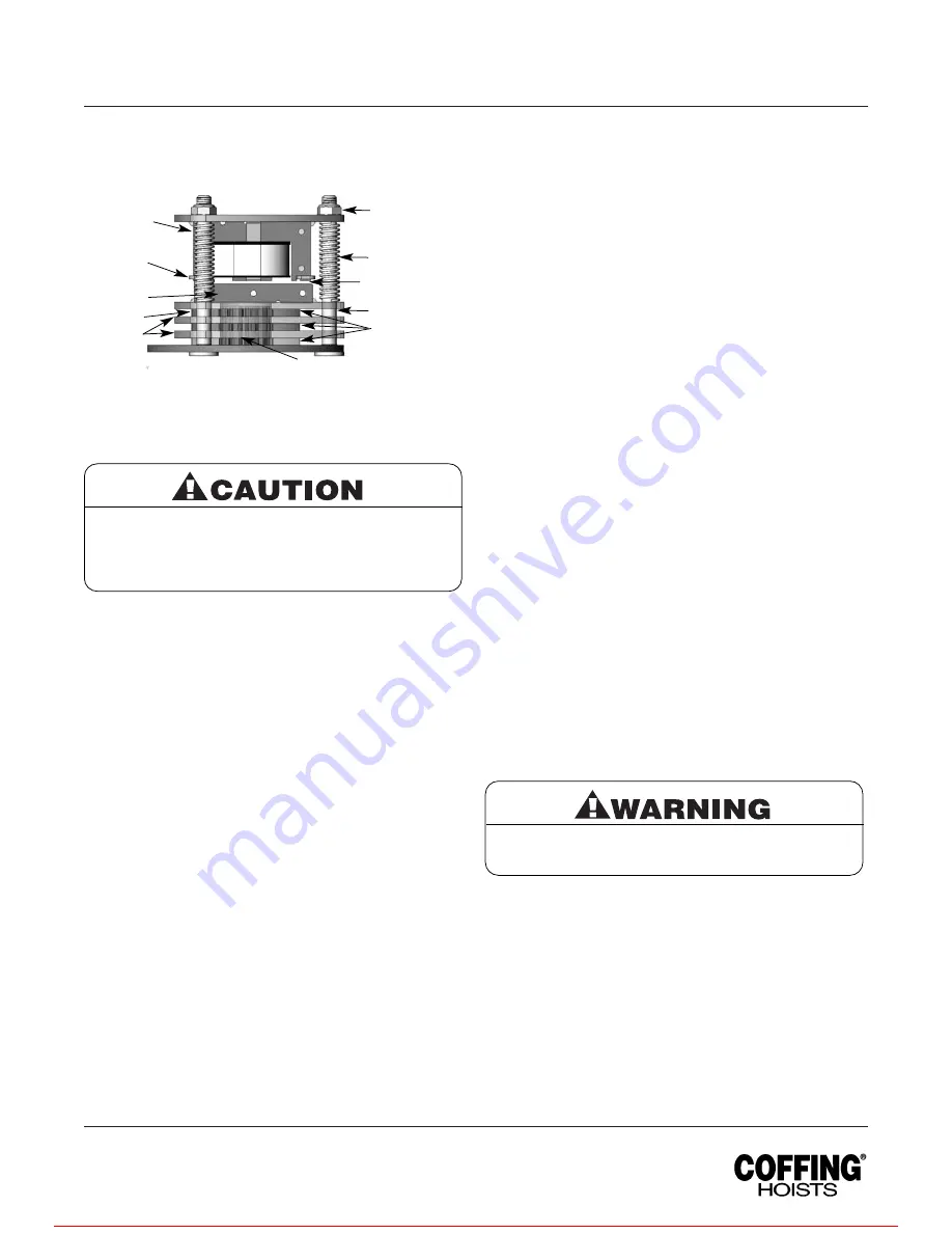
Be sure the bottom of the armature does not bear
against the splined adapter “H”. As adjustments are
made, the built-in clearance will be reduced. When
this clearance is gone REPLACE BRAKE DISCS.
Minimum allowable disc thickness is .162". See
Figure 13 for further illustration.

Remove load and disconnect lifting motor from
power supply before starting to do any repairs or to
take any sections apart.

Country Club Road
P.O. Box 779
Wadesboro, NC 28170 USA
TEL: (800) 477-5003
FAX: (800) 374-6853

Figure 4 — Brake Assembly

Gap

F

G

X

B

E

A

X

D

H

C

For more information contact: Sievert Crane and Hoist, (708) 771-1600, [email protected], www.sievertcrane.com

Summary of Contents for Concert Series

Page 1: ...r each operator should become thoroughly familiar with all warnings instructions and recommendations in this manual Retain this manual for future reference and use Forward this manual to the lifting motor operator Failure to operate the equipment as directed in the manual may cause injury Should you have any questions or have problems with this product please call Coffing Hoists at 800 477 5003 UJ...

Page 2: ...d chain or hook to be used as an electrical or welding ground 20 NOT allow the load chain or hook to be touched by a live welding electrode 21 NOT remove or obscure the warnings on the lifting motor 22 NOT operate a lifting motor on which the safety placards or decals are missing or illegible 23 NOT operate a lifting motor unless it has been securely attached to a suitable support 24 NOT operate a...

Page 3: ...d cause widespread damage if dropped The lifting of loads which could explode or create chemical or radioactive contamination if dropped requires fail safe redundant supporting devices which are not incorporated into this lifting motor LIFTING OF GUIDED LOADS This lifting motor is recommended only for lifting freely suspended loads and is not for use in the lifting of guided loads including dumbwa...

Page 4: ...ave a load suspended in the air unattended 19 Always remove load before making repairs 20 Do not remove or obscure capacity or warning decals INSTALLATION POWER CONTROL SYSTEM REQUIREMENTS The UJC must be connected to a power and control system that is properly designed to operate the lifting motor and to handle the power consumption of the motor Note the motor amperages listed on page 3 Be aware ...

Page 5: ...s equipped with a factory calibrated overload limiting clutch that will permit the lifting of loads within its rated capacity but will prevent the lifting of damaging overloads while the lifting motor is being operated If the load being lifted exceeds the lifting capability of the overload clutch the motor will continue to run causing overheating of both the clutch and motor This condition should ...

Page 6: ...ease the brake 3 Use several quick releases instead of holding brake open continuously Do not exceed normal lowering speed HOOKS Refer to Figure 2 1 Inspect hooks once daily for cracking extreme wear or spreading Replace hooks showing any of these signs If the throat openings are spread wider than the maximum permissible 15 increase listed here the hooks have been overstressed and must be replaced...

Page 7: ...12th link with the two stop halves positioned with their tapered ends pointing towards the lifting motor Slide the sleeve over the halves and attach the retaining ring If you are not using a chain container attach the slack end of the new chain to the shackle on the side of the unit using the split link DO NOT allow twists in the chain 12 Adjust the lower limit switch See ADJUSTING LOWER LIMIT pag...

Page 8: ...the lifting motor to the power supply Be sure the green ground wire is properly grounded 2 Check the direction of hook travel See INSTALLING THE LIFTING MOTOR page 5 3 Carefully operate to upper limit and observe if it stops automatically at desired level Do not allow load block to run into the lifting motor housing this will damage the lifting motor Maintain a minimum clearance of 2 from the lift...

Page 9: ...ever apply grease to the chain Gearing The gearbox of this lifting motor is filled at assembly with 1 pints of SAE 90 EP gear oil To check oil level hang the unit by the suspension hook the unit and decals will be upside down and remove the oil level check plug With the lifting motor hanging level the gear oil should be even with the hole Bearings All bearings except hook and idler sheave bearings...

Page 10: ...See Figures 14 and 15 3 Remove the four motor mounting bolts attaching the motor to the housing It will come loose at the motor coupling 4 Inspect the motor coupling motor shaft and all the bearings Replace as necessary 5 Install new or repaired motor according to the wiring diagram located inside the electrical cover or Figures 7A 7B and 7C Gearing Use the Replacement Parts List for Basic Unit an...

Page 11: ...ifting Motors POWER CORD PRECAUTIONS WITH 1 PHASE LIFTING MOTORS Electric lifting motors require a sufficient power supply It is especially important with single phase voltage to ensure that the conductors running to the lifting motor from the power source are adequate in size to handle the power requirements of the lifting motor Inadequate power cables and branch circuits will cause low voltage h...

Page 12: ...s Factory supplied wiring diagrams will have numbers beginning with 985 for 575V 987 for 208V 988 for 380V and 989 for 415V Country Club Road P O Box 779 Wadesboro NC 28170 USA TEL 800 477 5003 FAX 800 374 6853 For more information contact Sievert Crane and Hoist 708 771 1600 parts sievertelectric com www sievertcrane com ...

Page 13: ...n or short circuit check all connections in control circuit Check for burned contacts Replace as needed 6 Faulty capacitor single phase lifting motor only 6 Check starting capacitor on motor Replace if necessary 7 Worn overload limiting clutch 7 Replace overload clutch assembly 8 Loose screw clamps 8 Ensure that screw clamps are tightened on the terminal blocks and reversing contactor Hook lowers ...

Page 14: ... Contactor other Electrical Loose connections burned or pitted contacts Apparatus Supporting Structure and Trolley Damage or wear which restricts ability to support if used imposed loads Nameplates Decals Missing damaged or illegible Warning Labels NOTE Refer to Maintenance and Inspection Sections of the Lifting Motor Maintenance Manual for further details FREQUENCY OF INSPECTION Frequent Indicate...

Page 15: ...hing Assembly INSPECTOR S REPORT ITEM REMARKS LIST DEFICIENCIES AND RECOMMENDED ACTION Figure 8B Recommended Inspector s Report NOTE All bearings except hook and idler sheave bearings are prelubricated and sealed This lubrication schedule is based on a lifting motor operating in normal environment conditions Lifting motors operating in adverse atmospheres containing excessive heat corrosive fumes ...

Page 16: ...M405A01S 1 11 Latch Kit Assembly 4X1305 1 12 Hook Retainer JM285 1 13A Swivel Hook Retainer JM49 2A 1 13B Swivel Hook Retainer JM49 2B 1 14 Coffing Decal 677J7R 2 15 Capacity Decal 1 2 ton JLC675R 05 1 1 ton JLC675R 10 1 2 ton JLC675R 20 1 16 UJC Decal 677JM8 2 17 Coffing Decal JM677R 2 Figure 10 Basic Unit Country Club Road P O Box 779 Wadesboro NC 28170 USA TEL 800 477 5003 FAX 800 374 6853 3 12...

Page 17: ...Assembly 1 4 End Shield 35EP3100D15 1 5 Rear Bearing 500K3 1 6 Front Bearing 732012C 1 7 Shim Washer JL4301 01 1 8 Thru Bolt 1 Speed HA3100A56 4 9 10 Spring Lockwasher H4082P 4 Ref Part No Description No Qty Ref Part No Description No Qty Country Club Road P O Box 779 Wadesboro NC 28170 USA TEL 800 477 5003 FAX 800 374 6853 Refer to the motor nameplate for part number voltage full load amperage ho...

Page 18: ...earing 732012C 1 7 Shim Washer JL4301 01 1 8 Thru Bolt HA3100A56 4 9 10 Spring Lockwasher H4082P 4 Ref Part No Description No Qty Country Club Road P O Box 779 Wadesboro NC 28170 USA TEL 800 477 5003 FAX 800 374 6853 Refer to the motor nameplate for part number voltage full load amperage horsepower and other motor information 2 6 8 1 9 7 5 4 3 For more information contact Sievert Crane and Hoist 7...

Page 19: ... 1 208V 853JL5 1 380V 853JL6 1 415V 853JL7 1 10 Locknut H3978 3 11 Adapter JM142 1 12 Screw H2976P 3 13 Retaining Ring H5501 2 14 Shading Coil 860J1 2 Shading Coil Adhesive H7812 1 15 Lockwasher H4134 3 16 Spacer 1 2 hp 141J2 3 Ref Description Part Qty Ref Description Part Qty No No No No Note 115 230V 1Phase models use 115V brake coils 230 460V 3 Phase models use 230V brake coils Country Club Roa...

Page 20: ...tail 299JG4 2 1 10 Panel Standoff Spacer 200J4 3 11 1 4 Internal tooth Lockwasher H4134 3 12 1 4 20UNC X 4 Screw H1027P 3 13 8 32UNC X 5 16 Screw H2751 2 14 8 External tooth Lockwasher H4158 2 15 1 4 Flatwasher H4002P 1 16 10 24UNC X 1 2 Screw H2970 2 Ref Description Part Qty Ref Description Part Qty No No No No Parts List for Electrical Parts 3 Phase Coil voltage of the contactor and the secondar...

Page 21: ...Screw H1027P 3 15 8 32UNC X 5 16 Screw H2751 2 16 8 External tooth Lockwasher H4158 2 17 1 4 Flatwasher H4002P 1 18 10 24UNC X 1 2 Screw H2970 2 19 Can Mounting Bracket JM811 2 20 SINPAC Starting Switch 839J3 1 21 Capacitor JL810 4 1 Ref Description Part Qty Ref Description Part Qty No No No No Parts List for Electrical Parts 1 Phase Coil voltage of the contactor and the secondary voltage of the t...

Page 22: ... 6 32UNC X 1 Screw H1402P 4 15 6 32UNC Elastic Locknut H3944 4 16 Mounting Plate 129J1 1 17 Frame and Guide Assembly 258JG7 1 18 End Plate 258J8 1 19 8 32UNC X 3 8 Screw H2741P 2 20 Drive Pinion 427J1 1 21 Retaining Ring H5520 1 22 10 24UNC X 3 8 Screw H2981P 2 Ref Description Part Qty Ref Description Part Qty No No No No Figure 16 Limit Switch Parts Country Club Road P O Box 779 Wadesboro NC 2817...

Page 23: ... Cable Length PBC2100 16 1 Special Drop PBC2100 S 1 4 Enclosure 36998 1 5 Gasket 36986 1 6 Contact Assembly 36987 1 Includes item 7 7 Button Assembly 36988 1 8 Grommet 36989 1 Hardware Kit 36939 1 Includes items 9 16 Warning Tag 687K3W 1 Ref Description Part Qty Ref Description Part Qty No No No No Country Club Road P O Box 779 Wadesboro NC 28170 USA TEL 800 477 5003 FAX 800 374 6853 Equal to cabl...

Page 24: ... 14 14 16 17 6 24 33 25 27 28 12 32 30 34 34 NOTE Orient output gear 32 with long boss towards gear housing 2 on 1 2 ton under models and towards transmission cover 3 on 1 2 ton models 18 16 19 20 18 NOTE This stage of gearing is not required on 32 FPM models For more information contact Sievert Crane and Hoist 708 771 1600 parts sievertelectric com www sievertcrane com ...

Page 25: ...diate Pinion 1 2 ton 16 fpm JL402A 1 1 2 ton JL403A 1 21 Bearing 500K39 2 22 Output Pinion JL401 1 23 Overload Clutch Assembly 1 2 ton 16 fpm 591JG16 1 1 2 ton 32 fpm 591JG21 1 1 2 ton 591JG17 1 24 Retaining Ring H5503 2 25 Bearing 500K28 1 26 Bearing P003255 1 27 Spacer Load Sheave JM127 1 28 Load Sheave 9 32 Chain JF16 3 1 29 Load Sheave Shaft JM132 1 30 Stub Shaft Limit Switch Drive JM140 1 31 ...

Page 26: ...SA TEL 800 477 5003 FAX 800 374 6853 2 Ton Models 1 Ton Under Models 1 4 5 3 2 6 9 18 8 19 15 14 26 24 15 28 32 12 29 7 25 31 16 14 30 23 22 24 7 21 13 17 13 20 10 11 For more information contact Sievert Crane and Hoist 708 771 1600 parts sievertelectric com www sievertcrane com ...

Page 27: ...Ton Under 3JG20S 1 21 Bottom Block Assembly for 2 Ton JF914 6 1 22 3 8 24 Hex Locknut H3964P 2 23 Load Block Screw H2403P 2 24 Load Block Frame JF30 1 2 25 Sheave Shaft Assembly JF917 1 1 26 Sheave Shaft JF122 1 1 27 Sheave Bearing Assembly JF916 1 28 Roll Pin H5234 2 29 3 8 24 Hex Locknut H3991P 1 30 Bearing JF511 1 31 Latch Kit 4X1305 1 32 Bottom Hook Assembly with Latch for 2 Ton 3KG1W 1 Parts ...

Page 28: ...o the original purchaser without charge and the lifting motor will be returned transportation prepaid This warranty does not apply where deterioration is caused by normal wear abuse improper or inadequate power supply improper or inadequate maintenance eccentric or side loading overloading chemical or abrasive actions excessive heat unauthorized modifications or repairs or use of non Coffing repai...

Reviews: