background image

Code Blue


 259 Hedcor Street 

 Holland, MI 49423 USA 

 800.205.7186 

 www.codeblue.com

GU-163-A

page 2 of  27

CB RT

Administrator Guide

WARNING

ONLY QUALIFIED PERSONNEL SHOULD INSTALL THESE UNITS.  THE INSTALLATION 

SHOULD CONFORM TO ALL LOCAL CODES.  IN SOME COUNTRIES, A CERTIFIED ELECTRI-

CIAN MAY BE REQUIRED.

NOTICE TO USERS

Copyright © Code Blue Corporation.  All rights reserved.  This guide or software described herein, in 

whole or part, shall not be reproduced, translated or reduced to any machine-readable form without 

prior written approval from Code Blue Corporation.

CODE BLUE CORPORATION PROVIDES NO WARRANTY WITH REGARD TO THIS GUIDE, THE 

SOFTWARE OR OTHER INFORMATION CONTAINED HEREIN AND HEREBY EXPRESSLY DIS-

CLAIMS ANY IMPLIED WARRANTIES OF MERCHANTABILITY OR FITNESS FOR ANY PARTICU-

LAR PURPOSE WITH REGARD TO THIS GUIDE, THE SOFTWARE OR SUCH OTHER INFORMA-

TION.  IN NO EVENT SHALL CODE BLUE CORPORATION BE LIABLE FOR ANY INCIDENTAL, 

CONSEQUENTIAL, OR SPECIAL DAMAGES, WHETHER BASED ON TORT, CONTRACT, OR 

OTHERWISE, ARISING OUT OF OR IN CONNECTIONS WITH THIS GUIDE, THE SOFTWARE 

OR OTHER INFORMATION CONTAINED HEREIN OR THE USE THEREOF.

Code Blue Corporation reserves the right to make any modifications to this guide or the information 

contained herein at any time without notice.  The software described herein may also be governed 

by the terms of a separate user license agreement.

Code Blue

®

 is a registered trademark of Code Blue Corporation.  

Summary of Contents for CB RT

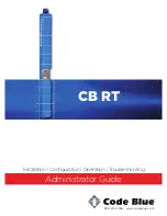
Page 1: ...800 205 7186 www codeblue com Administrator Guide Installation Configuration Operation Troubleshooting CB RT...

Page 2: ...THIS GUIDE THE SOFTWARE OR OTHER INFORMATION CONTAINED HEREIN AND HEREBY EXPRESSLY DIS CLAIMS ANY IMPLIED WARRANTIES OF MERCHANTABILITY OR FITNESS FOR ANY PARTICU LAR PURPOSE WITH REGARD TO THIS GUID...

Page 3: ...ts 6 5 Technical Features 7 6 Exploded View 8 7 Power Requirements 10 8 CB RT Installation Instructions 13 9 Overhead Camera Mount Installation Instructions 15 10 Standard Wiring 17 11 PoE Wiring 18 1...

Page 4: ...e by security when activated The exclusive analog InterAct and VoIP speakerphones are designed for maximum reliability vandal resistance auxiliary functions mass notification control and fault monitor...

Page 5: ...fore operation Consult the User Guide or Admin istrator Guide enclosed with the unit or go to www codeblue com Support Downloads to read or download manuals 4 If you are installing IP speakerphones pl...

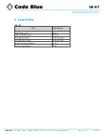
Page 6: ...codeblue com GU 163 A page 6 of 27 CB RT Administrator Guide 4 Spare Parts CB RT Part Part Number LED Strobe Light 40159 LED Faceplate Light 40196 Faceplate Screws 41544 6 pack Access Door Screws 415...

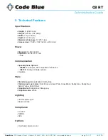
Page 7: ...x 20 02 cm Power Standard 12 24V AC DC Optional 120 240 277V AC PoE Communication Speakerphone Options IP5000 Full duplex SIP compatible VoIP phone IA4100 Analog full duplex phone Hardwire Style Stand...

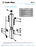
Page 8: ...ed to assist in component identification Reference the model and serial number from the unit ID tag and contact manufacturer to confirm replacement part version and availability ITEM DESCRIPTION QTY 1...

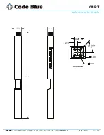
Page 9: ...nd MI 49423 USA 800 205 7186 www codeblue com GU 163 A page 9 of 27 CB RT Administrator Guide 113 51 10 00 8 00 2 1 4 5 6 2 13 4 26 4 00 6 00 45 TYP 11 06 16 00 105 50 SIDE VIEW BASE PLATE DETAIL SCAL...

Page 10: ...05 12 60 0 30 24V DC 1 05 25 20 0 60 CB 5 s 5 p 24V AC 0 48 11 52 0 28 12V DC 0 67 8 04 0 19 24V DC 0 67 16 08 0 39 CB 9 s 24V AC 0 26 6 24 0 15 12V DC 0 43 5 16 0 12 24V DC 0 43 10 32 0 25 CB 2 e 24...

Page 11: ...31 31 44 0 75 12V DC 1 05 12 60 0 30 24V DC 1 05 25 20 0 60 CB 5 s 5 p 24V AC 0 48 11 52 0 28 12V DC 0 67 8 04 0 19 24V DC 0 67 16 08 0 39 CB 9 s 24V AC 0 26 6 24 0 15 12V DC 0 43 5 16 0 12 24V DC 0...

Page 12: ...0 25 CB 9 s 24V AC 0 11 2 64 0 06 12V DC 0 19 2 28 0 05 24V DC 0 19 4 56 0 11 CB 2 e 24V AC 0 29 6 96 0 17 12V DC 0 39 4 68 0 11 24V DC 0 39 9 36 0 22 CB 2 a 24V AC 0 33 7 92 0 19 12V DC 0 43 5 16 0 1...

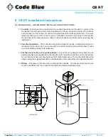
Page 13: ...The foundation should be at least 18 inches in diameter and the cor rect depth for the frost line in your area with a minimum depth of at least three feet Follow your local building codes for foundati...

Page 14: ...d methods to avoid possible injury and or damage 2 3 Secure the unit Access the mounting studs through the door on the side of the unit and tighten the mounting nuts onto the anchor bolts This may be...

Page 15: ...bolts with your 3 8 wrench in a crisscross pattern to ensure even pressure until it is snug against the outside of the enclosure INSTALLING THE CAMERA Camera and wiring supplied by others is installed...

Page 16: ...h any questions or concerns Email customerservice codeblue com Phone 616 392 8296 Opt 2 51 38 2 50 1 00 A B C D 4 4 3 3 2 2 1 1 XXXXXX NEXT LEVEL XXXXXX CUSTOMER DWG NO XXXXXX CUSTOMER DRAWING NO X 12...

Page 17: ...inistrator Guide 10 CB RT Standard Wiring For Incoming Power 24V AC DC or 100 277V AC Incoming High Voltage AC IP5000 IA4100 Beacon Strobe Faceplate LED Bar To Ground To Ground RJ45 RJ11 Incoming Data...

Page 18: ...reet Holland MI 49423 USA 800 205 7186 www codeblue com GU 163 A page 18 of 27 CB RT Administrator Guide 11 PoE Installation Instructions For Incoming Power POE IP5000 Beacon Strobe Faceplate LED Bar...

Page 19: ...odeblue com GU 163 A page 19 of 27 CB RT Administrator Guide 12 Locating Unit Serial Numbers Remove the access plate cover with the special security bit The serial number will be listed on the manufac...

Page 20: ...ng a separate conduit from the power and be run so as to extend a minimum of two feet out of the phone opening 2 0 CONNECT THE POWER WIRES 2 1 Make the connections Locate the grounding lug and connect...

Page 21: ...LASH MODE connect both YELLOW control wires together i e CLOSED ON PHOTOCELL FEATURE S 1050 MODEL The Steadyburn Mode will be ON in dark or night ambient environments and OFF in bright or daylight amb...

Page 22: ...isconnected for 20 seconds BEFORE reapplying When power is reapplied the unit will operate as programmed above NOTE If you do not leave power disconnected for 20 seconds before reapplying power the li...

Page 23: ...effectively by re motely controlling emergency communication devices with an easy to use Graphical User Interface GUI You also will have the ability to open gates and AED access doors turn LED beacon...

Page 24: ...s are tight and clean Verify no stains exist around gasket areas Stains indicate leaking and gasket should be replaced Verify moisture weep hole on cabinet bottom is open and unobstructed Verify botto...

Page 25: ...to The Surface Care Frequency table below provides general guidelines to assist in configuring a schedule Please note that the frequency of care required to guard the Code Blue unit s surface from da...

Page 26: ...t for this product while under warranty is available at www codeblue com support In Case of Breakdown In case of system breakdown discontinue use and contact Tech Support at ts codeblue com or call 80...

Page 27: ...rces guides 8 Phone Enclosures Administrator Guide www codeblue com resources guides 9 Stainless Steel Maintenance Guide www codeblue com support 10 IA4100 Administrator Guide www codeblue com resourc...

Reviews: