background image


45 


9.  Torque to 12 Nm (105 in-lb) in the pattern shown in figure 28. 
10.  Trim away any excess gasket material if necessary.  
 

NOTE:

 Check engine mount holes for excess material that may cause problems 

in engine installation. 
 
11.  Install the piston with new wrist pin bearing and, pin and clips. 
 
CAUTION: 
Be sure to align the piston such that the arrow on the top piston surface points to 
the exhaust (front of bike/engine) and put assembly lube on the connecting rod 
bearing. 
 
12.  Install the piston rings. 
 
CAUTION: 
Ring end gap should be no less than 0.25 mm (0.010”) and no 
more than 0.64mm (0.025”) 
 
13.  Install the base gasket. 
14.  Install the cylinder being sure that the piston rings are 

properly aligned with the indexing pins. 

 
CAUTION: 
Never force the cylinder. If resistance is felt, determine the 
problem and solve it. Once installed slightly rotate the cylinder 
back and forth insuring that the rings are properly seated. 
 
15.  Install cylinder head insert. 
 

NOTE:

 A light application of silicone grease can help hold the 

O-RINGs into position during assembly. 
 
16.  Pressure test the engine insuring an acceptable leakdown 

rate. 

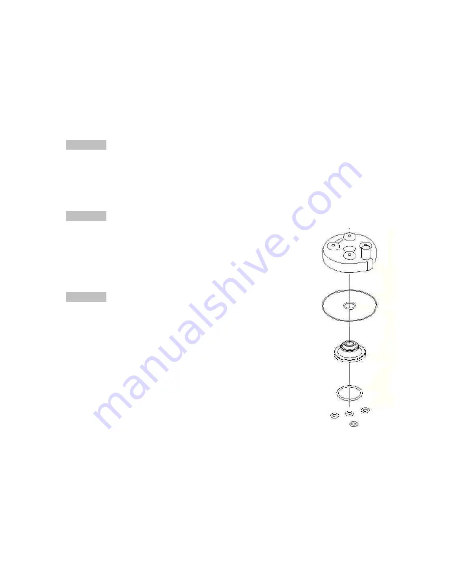
17.  Install O-RINGs as shown in figure 29. 

Figure 29 

18.  Install the cylinder head. 
19.  Install the washers (with flat side down) and nuts. Torque to 105 in-lb (12 

Nm) 

20.  Install reed and inlet manifold with new gaskets (105 in-lb, 12 Nm) applying 

1104 gasket sealer to both sides of all gaskets. 

21.  Leak check the engine to 20 psi to ensure proper seal. 
22.  Install stator reinstalling the grommet and wires (snug the bolts). 
23.  Install the rotor per 

Rotor Installation

 section, under the

 S3: Ignition

 portion of 

this manual. 

Summary of Contents for 2006 King 50

Page 1: ...2006 King 50 Owners Parts Service Tuning...

Page 2: ...Cobra dealer log on to www cobramotorcycle com or call 330 549 9600 If you need technical assistance contact your local dealer or call the Cobra Technical Support Hotline at 330 549 9603 Cobra Motorcy...

Page 3: ...ENDED FOR EXPERIENCED RACERS ONLY AND NOT FOR BEGINNERS IT IS YOUR RESPONSIBILITY AS THE OWNER OF THIS COBRA MOTORCYCLE OR AS THE PARENT OR LEGAL GUARDIAN OF THE OPERATOR TO KEEP THIS COBRA MOTORCYCLE...

Page 4: ...KE MAINTENANCE 13 AIR FILTER CLEANING 15 FORK OIL REPLACEMENT 17 PARTS 19 PARTS AIRBOX INLET SYSTEM 19 PARTS BARS AND CONTROLS 20 PARTS CARBURETOR 21 PARTS COOLANT SYSTEM 22 PARTS ELECTRICAL SYSTEM 23...

Page 5: ...ERVICE 40 ENGINE SERVICE 40 Engine Removal 41 Complete Engine Disassembly Procedure 42 Top End Disassembly Procedure 42 Splitting the Cases 43 Engine assembly 44 CLUTCH 46 IGNITION 51 COOLING SYSTEM 5...

Page 6: ...log advance Spark plug Champion 8339 1 8332 1 hotter 8904 1 colder Gap 0 023 0 025 0 58 0 64 mm Ignition timing 0 040 1 02 mm Before To Dead Center BTDC Fuel type High octane pump gasoline RACE FUELS...

Page 7: ...on Pre filter for the airbox Sprockets o Front o Rear Suspension Springs Weight of Rider lb Fork Spring Shock Spring Less than 51 0 23 kg mm KCKG1223 gray 3 5 kg mm SCKGFX35 51 60 0 25 kg mm KCKG1206...

Page 8: ...ont axle nut 25 300 34 M12 x 1 25 Engine mount bolts 22 265 30 M8 X 1 25 Swingarm Pivot 21 250 28 M14 X 2 0 Intake manifold bolts 4 6 55 6 2 M6 X 1 0 Rear Axle Bolt 25 300 34 M12 X 1 25 Rear Sprocket...

Page 9: ...period operate the bike on the stand with a combination of idle and high RPM operation avoid prolonged high RPM but spin the rear wheel good at least once or twice per minute Allow bike to cool Ride...

Page 10: ...formulated Cobra Venom 2 cycle Race Oil Turn the fuel on by rotating the fuel petcock knob to the vertically downward position reserve position is horizontally forward CAUTION For best results from y...

Page 11: ...out the crankcase vent during riding 7 New chains will stretch on first use Never install a new chain prior to a race Always break them in during practice 8 Your Cobra Motorcycle has a 10 digit VIN Ve...

Page 12: ...s off because of lack of airflow around the stator 2 If you ever need to weld anything on the bike disconnect the spark plug cap unplug the ignition disconnect the kill switch scrape the paint bare ne...

Page 13: ...h oil drain hole 3 Remove the oil drain plug located on the right side of the engine on the clutch cover near the brake lever figure 1 Figure 1 4 After it has drained reinstall the plug being sure tha...

Page 14: ...e Maintenance CAUTION Too little brake pedal free play will allow the brake pads to drag causing the pads to wear prematurely and possible engine component failures Too much free play will not allow t...

Page 15: ...figure 2b 1 Loosen the lock nut 10mm 2 Undo the free play locking clip from around the brake adjustor plunger with your hand by pushing it forward 3 Slide the pin of the locking free play locking cli...

Page 16: ...cles from the airbox between the filter location and the carburetor NOTE Cobra has available a carburetor cover that allows easy cleaning of the airbox 1 Remove the air boot 2 Install the cover RCMU01...

Page 17: ...figure A2 Figure A2 5 Squeeze the two finger tabs together on the wire retainer and install into the airbox while aligning the bottom guiding tabs legs with the arrows on the filter figures A3 A4 Fig...

Page 18: ...d retainer should look like figure A7 with the filter material extending beyond the perimeter of the wire retainer Figure A7 NOTE Make sure you change or clean your filter after each moto We recommend...

Page 19: ...table pan tray or container e Work the damper rod up and down several times f Allow it to drain completely Assembly procedure 1 Fill the fork leg with 4 4 oz 130 ml 7 wt fork oil 2 Measure the fork oi...

Page 20: ...ACKET MUDFLAP 7 HCBB0612 M6X12 BUTTON HEAD BOLT 8 MCKGHO03 HOSE CLAMP AIRBOX TO BOOT 9 RCKG0505 AIR BOOT 10 MCKGHO01 HOSE CLAMP BOOT TO CARB 11 MCKGHO04 HOSE CLAMP CARB TO MANIFOLD 12 ECKG0203 INLET M...

Page 21: ...RAKE LEVER W BALL 6 BCKG0024 BRAKE PERCH ASSY W LEVER BALL NOT SHOWN BAKG0004 SHIELDED BRAKE HOSE ASSEMBLY 7 FCMU0019 THROTTLE CABLE 8 HCBC0806 SOCKET HEAD CAP SCREW M8 X 30 4 PER 9S TKMU0404M BAR MOU...

Page 22: ...7 TOP CARB GASKET 14 RCMU0004 SLIDE SPRING 15 RCMU0205 NEEDLE RETAINER PLATE 16 RCMU0007 NEEDLE CLIP 17 RCMU0204 CHOKE ASS Y 2001 CM 20 RCMU0009 FUEL MIXTURE SCREW 21 RCMU0011 IDLE ADJUSTMENT SCREW 25...

Page 23: ...3 MCMUHO05 RADIATOR HOSE TOP LEFT 4 MCKGHO02 RADIATOR HOSE BOTTOM RIGHT 5 MCMUGR03 MOUNTING GROMMET 3 PER 6 FCMU0006 RADIATOR MOUNTING BRACKET TEARDROP 7 HCBF0616 FLANGE HEAD BOLT M6X16 8 MCMUCL07 HOS...

Page 24: ...HCBC0516 SCREW M5 X 16 2 PER 5 HCCN0000 5MM CLIP NUT 2 PER 6 ICMU0018 STATOR 7 HCBC0535 5mm x 35 SOCKET HEAD CAP SCREW 2 REQ D 8 HCBC0525 5mm x 25 SOCKET HEAD CAP SCREW 9 HCWF0504 WASHER FOR STATOR 3...

Page 25: ...SE ALIGNEMENT 2 REQ D 11 ECMU0099 OUTPUT SHAFT TRANSMISSION WITH GEAR 12 ECMU0100 SECONDARY SHAFT TRANSMISSION WITH GEAR 13 ECMU0001 BEARING TRANMISSION SECONDARY SHAFT 14 ECKG0031 BEARING OUTPUT SHAF...

Page 26: ...0141 HUB CFD 12 ECMU0142 PLATE CFD 2 REQ D 13 ECMU0143 PAPER CFD 2 REQ D 14 ECMU0144 GEAR CFD 15 ECMU0145 SPRING WASHER CFD 16 HCWF0002 WASHER FLAT CFD 13MM 17 HCNS1202 NUT CFD 20 LEFT HAND THREAD BLU...

Page 27: ...TER PUMP SHAFT 5 ECKG0073 IMPELLER WATER PUMP 6 ECKG0004 RETAINER WATER PUMP ASSEMBLY 7 HCBB0003 5MM X 12 BUTTON HEAD STAINLESS 8 HCWF0501 FLAT WASHER 9 ECKG0175 WATER PUMP PULLEY FAN TYPE DRIVEN 10 E...

Page 28: ...9 ZCMUOR07 O RING EXHAUST FLANGE 10 ECMU0086 EXHAUST FLANGE NOT SHOWN ZCMOTE11 O RINGS PIPE TO FLANGE 2 REQ D 11 HCBC0602 M6X20 EXHAUST FLANGE SCREW 2 REQ D 12 HCNS0601 6mm Nut 13 HCWF0601 6MM FLAT WA...

Page 29: ...MET WASHER 2 REQ D 8 HCBF0635 M6X35 FLANGE HEAD BOLT NOT SHOWN HCHA0003 6MM CLIP NUT FOR FRONT PIPE MOUNT 9 XCDC0003 SILENCER NOT SHOWN XCMU0018 SILENCER PACKING 10 XCKG0009 PIPE SILENCER SEAL 11 MCMU...

Page 30: ...0 HCBC0625 SOCKET HEAD CS M6X25 4 REQ D 11 HCBC0806 CAP SCREW M8X30 4 REQ D 12S TCMU0404 BAR MOUNT KIT SHORT 2 REQ D 12T TCMU0403 BAR MOUNT KIT TALL 2 REQ D 14 HCBC1001 M10X45 SOCKET HEAD CAP SCREW 2...

Page 31: ...0001 DAMPER ROD ASSEMBLY 13 KAKG0025 MID VALVE ASSEMBLY STANDARD KAKG0026 MID VALVE ASSEMBLY LIGHT KAKG0027 MID VALVE ASSEMBLY HEAVY 14 KCKG0022 CARTRIDGE CAP 15 KCKG0019 DAMPER TUBE CARTRIDGE 16 KAKG...

Page 32: ...LT 9 MCMUGR03 GROMMET 2 REQ D PER BOLT 10 TCKG0001 ALUMINUM SPACER 11 HCWF1478 PIPE GROMMET WASHER 12 HCBH0880 FRONT ENGINE MOUNT BOLT M8X30 SHCS 13 HCNL0801 8MM LOCKNUT 14 HCBH1403 SWINGARM PIVOT BOL...

Page 33: ...VOT BOLT 10 BCBH0601 M6 X 20 HEX HEAD BOLT 11 HCNS0601 6MM NUT 12 TCMU0010 WIDE FOOTPEGS PAIR 13 TCMU0107 FOOTPEG SPRING 2 PER 14 HCBB0803 M8X40 BUTTON HEAD BOLT 2 PER 15 HCNL0801 8MM LOCK NUT 2 PER 1...

Page 34: ...for new fork bottoms 11 HCBF0616 M6 X 16 FLANGE HEAD BOLT 12 WCMUZT04 CABLE TIES 2 REQ D TO SECURE BRAKE LINE TO FORK GUARD 13 BCKG0031 BLEED KIT MULTIPLE SYRINGES FITTINGS HOSE 14 BRAKE FLUID 15 FCKG...

Page 35: ...E 3 WCKG1201 12 FRONT TUBE 4 WCKG0011 FRONT AXLE 5 WCMU0123 FRONT WHEEL SPACER X LARGE 6 WCMU0120 WHEEL BEARING 2 REQD 7 WCMU0032 WHEEL BEARING SPACER 8 WCMU0101 FRONT WHEEL SPACER LARGE 10 HCWF1202 F...

Page 36: ...MOUNT BOLT 1 PER SIDE NOT SHOWN HCWP0002 SHROUD WASHER 1 PER SIDE 5 TCMU0113 SIDE NUMBER PLATE SET NOT SHOWN HCBB0516 M5X16 NUMBER PLATE MTG SCREW 2 PER SIDE NOT SHOWN HCWP0002 NUMBER PLATE WASHER UP...

Page 37: ...11 BCKG0010 REPLACEMENT BRAKE HOSE 12 HCBF0635 M6X35 FLANGE HEAD BOLT 13 HCBF0620 M6X20 FLANGE HEAD BOLT 14 BCKG0013 CALIPER REAR BRAKE ACCESSORY BKKG0001 BRAKE PADS WITH E CLIP 15 BCKG0103 BRAKE CARR...

Page 38: ...REAR SPROCKET NO DAMPERS 7 WCMU0020 WHEEL BEARING BRAKE SIDE 9 HCBH0702 M7X30 HEX HEAD BOLT 10 PCMU0001 MASTER LINK 420 11 PCMU0100 CHAIN 420 X 100 12 WCMU0016 REAR AXLE 13 HCPA0002 AXLE HEAD FIXING P...

Page 39: ...LOCK RING 4 SCKGFX37 SHOCK SPRING 3 7 KG MM STANDARD SCKGFX35 SHOCK SPRING 3 5 KG MM LIGHT SCKGFX39 SHOCK SPRING 3 9 KG MM HEAVY 5 SCKGFX03 SPRING RETAINER BOTTOM 6 SCKGFX01 COLLAR SHOCK END MOUNT 7...

Page 40: ...NL1401 1 4 LOCKNUT 2 PER 12 HCBF0620 M6 X 20 FLANGE HEAD BOLT 2 PER 13 HCCC0000 BRAKE HOSE CLAMP 2 PER 14 HCPP0832 BRAKE HOSE CLAMP FASTNER 2 PER 15 HCBH1001 M10 X 40 LOWER SHOCK MOUNT BOLT 16 FCMU020...

Page 41: ...please call 330 549 9603 for details Engine Service One method for determining whether the top end of your engine needs rebuilt is to perform a WOT Wide Open Throttle kicking compression test Before p...

Page 42: ...end and transmission the engine must be removed from the frame Tools required 10 11 13 22 mm wrench 8 10 14 17 19 mm sockets 3 4 5 mm hex key Allen wrench 7 mm nut driver flat or Phillip screwdriver...

Page 43: ...ywheel holding tool and 14 mm socket remove the nut that secures the flywheel 4 Using the Cobra flywheel clutch puller MCMUTL68 remove the flywheel from the crankshaft 5 Remove the stator 5mm hex key...

Page 44: ...ng etc are found replace the cylinder 2 If deposits are all are found a Clean with muratic acid b Once the deposits are removed inspect for abrasions and missing surface coating i If there are abrasio...

Page 45: ...ouple months of hard racing Engine assembly CAUTION For any seals that are to be installed apply a light amount of grease to the seals ID assembly lube on all bearings and a small amount of Loctite to...

Page 46: ...ins CAUTION Never force the cylinder If resistance is felt determine the problem and solve it Once installed slightly rotate the cylinder back and forth insuring that the rings are properly seated 15...

Page 47: ...belleville washers on your 2006 Cobra are similar looking but different in geometry from prior years Do not mix old and new parts as damage will occur Cobra clutch puller assembly Figure 30 Figure 31...

Page 48: ...acked Clean the washers and bolt if you intend to reuse The spring stacks in your 2006 Cobra clutch will contain 11 individual springs and a flat washer configured as a 5 stack See figure 32 This clut...

Page 49: ...tch engagement thus decreasing the abruptness of clutch engagement softer hit Part Thickness mm inch HCWS0801 1 4 0 056 HCWS0802 1 2 0 047 HCWS0803 0 79 0 031 HCWS0804 0 64 0 025 HCWS0805 0 51 0 020 H...

Page 50: ...tle blipper CAUTION Sludge build up between the spring washers also keeps the clutch shoe from engaging fully and this will cause the clutch to start to slip So y ou will need to clean the sludge out...

Page 51: ...he clutch is likely to malfunction 4 Use fine emery paper on the center hole of the clutch and on the tapered section of the crankshaft 5 Apply a small amount of wicking bearing retainer green thread...

Page 52: ...use of the amount of heat generated by the clutch and engine during extended periods of riding it is advisable to remove the ignition cover afterward to allow the ignition to cool off The heat transfe...

Page 53: ...hole 3 Remove the four bolts from the ignition cover 4 Remove the water pump belt from the rotor and water pump shaft 5 Turn the crankshaft counterclockwise until it reaches top dead center 6 Set the...

Page 54: ...n the engine keeps the radiator fluid in circulation throughout the motor The air stream running through the radiator cools the radiator fluid Therefore dirty radiators additionally reduce the cooling...

Page 55: ...the system 4 Drain engine transmission oil by removing drain screw using a 13mm hex wrench item 2 in the figure below 5 Remove right side radiator hose and unscrew coolant fitting with a 8mm hex key...

Page 56: ...a of the seal If there is any sign of wear like a groove replace the shaft Figure 40 14 Reinstall new bearings seal open side toward impeller and impeller Clean all threads and use green wicking beari...

Page 57: ...ly Ultra black Hi Temp RTV silicon or Teflon pipe sealant to the tapered pipe threads of the coolant fitting before assembly NOTE Refill the coolant system with Liquid Performance Propylene Glycol bas...

Page 58: ...idle turn the screw in clockwise in 1 4 turn increments and rev the engine after each KING Carburetor Ref Drawing REF PART DESCRIPTION 1 RCMU0305 CARB SLIDE 2 RCMU0601 NEEDLE 3 ATOMIZER AU2 62 4 MAIN...

Page 59: ...slightly rich as opposed to slightly lean This is because an overly rich engine will just run poorly while an overly lean engine will seize potentially causing an expensive top end rebuild and a DNF...

Page 60: ...om the carburetor 4 Disassemble the carburetor 5 Immerse all the metal parts in a carburetor cleaning solution 6 After the parts are cleaned dry them with compressed air 7 Blow out the fuel passages w...

Page 61: ...Figure 44 The presence of light indicates that the reeds should be replaced or possibly turned over Exhaust The pipe is a crucial element to a motorcycle Any kinks dents or damage done to the pipe wi...

Page 62: ...before each ride Make sure the brake does not have any leaks by holding the lever in while checking hose connections Make sure the brake lever pressure is OK by pulling in on the lever and ensuring f...

Page 63: ...the bottom of the fork leg 22mm wrench 5 Pry the dust seal swiper from its position with a small screw driver 6 Using a pick remove the wire retaining ring holding the fork seals into place 7 Pop the...

Page 64: ...ust seal swiper into the groove in the upper tube 11 Reinstall the damper cartridge assembly to the fork leg Secure the large bolt with 22 mm wrench to 35 ft lb with green thread locking agent 12 Fill...

Page 65: ...shock is fully serviceable but it is recommended that only trained professionals should service your shock Contact Cobra or PR2 for questions and service of your King shock Shock preload Figure 47 Sh...

Page 66: ...h improper gearing Poor performance Not enough top end speed No snap Over heat clutch Premature failure of engine seals bearings electronics High clutch wear Condition Gear Taller Gear Lower Mud Sand...

Page 67: ...2 43 15 37 2 47 14 35 2 50 15 38 2 53 13 33 2 54 14 36 2 57 15 39 2 60 13 34 2 62 14 37 2 64 15 40 2 67 13 35 2 69 14 stock 38 2 71 15 41 2 73 13 36 2 77 14 39 2 79 15 42 2 80 13 37 2 85 14 40 2 86 1...

Page 68: ...k spring 2 2 1 Stiffer spring stiffer throughout the travel 2 2 2 Less stiff spring less stiff throughout the travel 2 3 Compression damping 2 3 1 Harder more damping slower adds resistance to the sus...

Page 69: ...Proactive Suspension Adjustments Once you have the suspension adjusted for decent overall feel you can make proactive adjustments when faced with different racing conditions Situation Actions Sand tra...

Page 70: ...stments Condition Mixture will be Required adjustment Cold air Leaner Richer Warm air Richer Leaner Dry air Leaner Richer Very humid air Richer Leaner Low altitude Standard None High altitude Richer L...

Page 71: ...adjustment To raise the idle turn the screw in clockwise in 1 4 turn increments and rev the engine after each adjustment To lower the idle turn the screw counter clockwise TOP END JETTING Adjust for c...

Page 72: ...case gasket 2 Engine is down on power a Clutch engagement is not set properly b Jetting is incorrect c Silencer needs repacked d Exhaust pipe i Has excess carbon buildup ii Has large dent in it e Com...

Page 73: ...ket drum 6 Engine won t idle a Idle knob needs adjusted b Carburetor jets are dirty Index Air Filter 15 Bars and Controls 20 Break In 8 Carburetor Parts 21 Service 56 Specifications 5 Chain Adjustment...

Page 74: ...Frame 31 Front Brake 33 Front Wheel 34 Ignition Water Pump 26 Plastic Seat 35 Rear Brake 36 Rear Wheel 37 Shock 38 Swingarm 39 Top End 27 Triple Clamps 29 Plastic Seat Parts 35 Pullers 60 Rear Brake A...

Reviews: