background image

 Important: Always read and follow operating instructions. 

• 19

Pressure Limiter Maintenance

Operating a tire changer with a defective, 
improperly adjusted, or by-passed pres-
sure limiter could cause an operator to 
accidentally over pressurize a tire, result-
ing in a tire explosion with severe injury or 
death to the operator or bystanders.

Always be sure that the pressure limiter is 
present and is operating properly.

Never inflate tire above manufacturer’s rec-
ommended pressure after bead is seated. 
Pressure limiter is set at 60 PSI. Any 
required inflation above 60 PSI should be 
performed in an inflation chamber/safety 
cage or securely mounted on the vehicle 
if an inflation chamber is not available. A 
tire explosion may cause personal injury or 
death to operator or bystanders.

The pressure limiter helps prevent inflation of stan-

dard size or larger tires or tubes beyond 60 PSI to 

minimize risk of explosion. This device is for the safety 

of the operator and bystanders. Proper operation of 

the pressure limiter is essential to safe operation of 

the machine.

Check operation of the pressure limiter as shown 

and described below at least monthly:

1.

 Remove tires and/or wheels from the machine.

2.

 Connect the inflation hose to an empty service 

tank with a pressure gauge (should read 0). Use a tank 

with at least 200 PSI pressure rating.

3.

 Depress inflation pedal to position 1 to start 

airflow through the hose and into the tank. Maintain a 

steady pressure for constant flow.

4.

 Watch the rising pressure on the tank gauge and 

the gauge on the machine. Machine gauge should 

cycle between check and inflation pressures while 

tank gauge climbs steadily. As tank pressure reaches 

60 PSI, the pressure limiter should stop the airflow 

automatically. Both gauges should read 60 PSI ± 5 

PSI.

5.

 Release inflation pedal. Check manual release 

valve function by pressing the button and releasing 

pressure from the tank until it reaches 50 PSI. Discon-

nect inflation hose, and release air inside tank.

6.

 Replace pressure limiter if it fails to cycle properly 

during inflation, if it fails to shut air supply off at 60 

PSI, or if it malfunctions in any other way. Do not oper-

ate machine with a faulty pressure limiter.
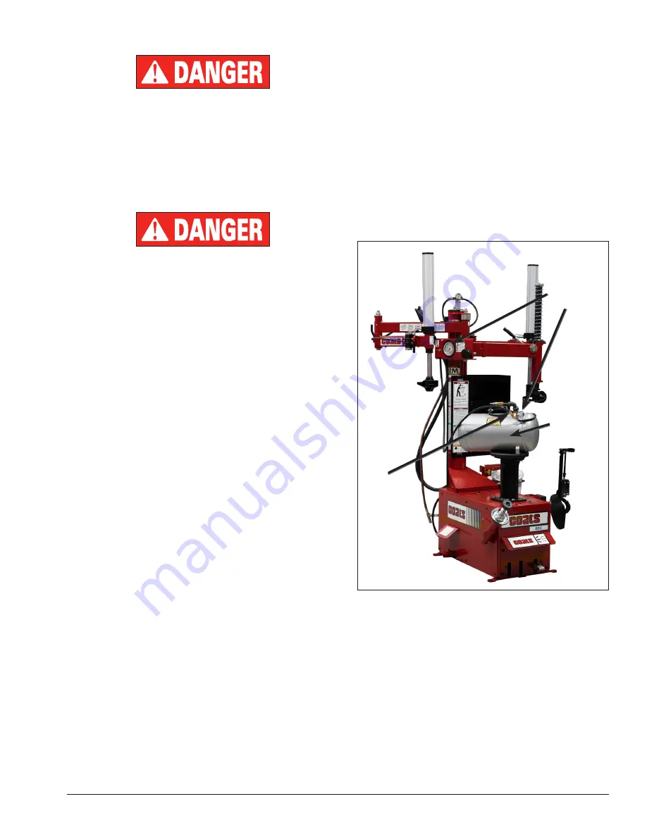
Watch 

Pressure on 

Both Gauges

Air Service 

Tank

Tire Changer 

Inflation Hose 

Connected to 

Tank

Summary of Contents for 80C

Page 1: ...rive LaVergne TN USA 37086 615 641 7533 800 688 6359 www coatsgarage com Manual Part No 85611918 00 HENNESSY INDUSTRIES LLC Manufacturer of COATS AMMCO and BADA Automotive Service Equipment and Tools Revision 8 20 80C Model Center ClampTire Changer For servicing single piece automotive and most tubeless light truck tire wheel assemblies Any other type including tube type agricultrual require speci...

Page 2: ...ructions 4 10 Tire Bead Loosening and Demounting 4 8 Tire Mounting 9 10 Inflation 11 13 Bead Sealing 11 12 Bead Seating 12 Inflation 13 Stages of Inflation on a ConventionalTire and Rim 14 MismatchedTires and Wheels 15 Custom and Special Wheels 16 TubeTypeTires 16 Maintenance Instructions 17 Duckhead Mount Demount Tool Cleaning 17 Duckhead Mount Demount Tool Adjustment 18 Robotic Arm Maintenance 1...

Page 3: ... width aspect ratio Nominal width of tire in millimeters Passenger car tire U S DOT tire identification number Severe snow conditions Tire ply composition and materials used Max load rating Treadwear traction and temperature grades Max permissible inflation pressure R A DIAL TUBELESS DOT MAL9 ABC036 T R E A D 4 P L I E S 2 X X X X X C O R D S I D E W A L L 2 P L I E S 2 X X X X X C O R D M A X L O...

Page 4: ... take the place of safe operating practices Always wear durable work clothing during tire service activity Loose fitting clothing should be avoided Tight fitting leather gloves are recommended to protect operator s hands when handling worn tires and wheels Sturdy leather work shoes with steel toes and oil resistant soles should be used by tire service personnel to help prevent injury in typical sh...

Page 5: ...nnessy Industries to help keep tire technicians safe By fol lowing the basic principles of R I M technicians can avoid situations that can cause catastrophic accidents like tire explosions R I M stands for read inspect and mount Read the tire size on a new tire before mounting to make sure it is the proper size for the wheel Inspect the wheel for cracks rust and or other dam age that could cause a...

Page 6: ...Your Unit Compare this illustration with the unit before placing it into service Maximum performance and safety will be obtained only when all persons using the unit are fully trained in its parts and operation Each user should learn the function and location of all controls Prevent accidents and injuries by ensuring the unit is properly installed operated and maintained 1 2 5 15 3 4 6 7 11 13 9 1...

Page 7: ...xtra leverage for runflat and low profile tires 11 Vertical Slide Locking Handle Locks and unlocks vertical slide and sets correct vertical position to maintain Duckhead tool wheel clearance 12 Tower Support for swing arm Robo Arm helper device and RoboRoller powered assist also air storage tank 13 DuckHead Combination Mount Demount Tool Mounts and demounts tire from wheel 14 Anti Rotation Extensi...

Page 8: ...e wheel section of this manual prior to servicing performance tire wheel combinations CAUTION Loosening the beads on a partially or fully inflated tire is unsafe and causes excess movement and friction against the bumper pads and excessive wear on pivots Deflate the tire completely to prolong the life of your machine 1 Deflate the tire completely by removing the valve core from the valve stem figu...

Page 9: ...ening figure 5 Figure 5 Apply Rubber Lubricant to Tire Beads 5 Place rubber protective cover on top of pedestal reverse mount only Align slot with anti rotation pin Figure 6 Place Protective Cover on Pedestal 6 Determine the mounting side of the wheel see figures 7a and 7b The mounting side is the narrow side of the drop center See figure 2 for more informa tion on the drop center Figure 7a Mounti...

Page 10: ...he center mount lock shaft through center of wheel figure 9 Push it down and turn 90 degrees clockwise to clamp wheel to pedestal figure 10 Now tighten by turning the knobs by hand in a clockwise direction Figure 9 Place Center Mount Lock through Wheel Center Figure 10 Tighten Tire Wheel Assembly to Pedestal 9 Move the swing arm into position Pull the lock ing handle forward to release the slide P...

Page 11: ...nce between the top of the rim edge and the bottom of the tool and 1 16 to 1 8 inch clear ance between the rim edge and the inside surface of the tool figure 14 This clearance will be maintained as long as the locking handle and adjustment knob are not changed The opera tor may swing the arm out of the way and back into place again without needing to reposition the tool when changing a like set of...

Page 12: ...n of the demount tool Hold the tool and bead in this position figure 17 Figure 17 Lift Bead Over Demount Tool 16 Depress the rotation pedal to rotate the wheel The Duckhead mount demount tool will guide the tire bead up and over the edge of the wheel Continue rotation until the upper bead is demounted NOTE Push down on the tire across from the demount tool during pedestal rotation to utilize the d...

Page 13: ...ire Run flat tires are not meant to be reused Damaged tires and or wheels may explode CAUTION When in doubt do not mount Never mount a tire and wheel handed to you by anyone without checking both tire and wheel for damage and to be certain the sizes match Used tires may have road hazard damage or mount demount damage inspect care fully Do not let untrained persons operate tire changer and keep bys...

Page 14: ...ockwise from Duckhead mount demount tool to allow bead to utilize drop center area of rim figure 25 If needed use the RoboRoller pow ered assist to keep the tire bead in the drop center area of rim figure 26 Fig 25 Use Robo Arm Helper Device To Hold Tire In Rim Drop Center 7 Depress rotation pedal and rotate tire until bead is mounted Be careful to ensure bead stays in the rim drop center in the a...

Page 15: ...e air pressure in the tire Whenever your foot is removed from the pedal it will return to this position Position 2 Tire Inflation This is the first activated position With the inflation hose attached using the clip on chuck to the tire valve and the pedal in this position line pressure is allowed to flow through the valve system and into the tire for inflation Correct tire pressure is not indicate...

Page 16: ...e changer If more than 40 PSI is permitted by tire manufacturer ALWAYS use safety cage and clip on chuck NEVER exceed recommended pressure after seat ing beads ALWAYS keep hands and entire body back from inflating tire An exploding tire wheel or bead sealing equipment may propel upward and out ward with sufficient force to cause serious injury or death to operator or bystander Check tire pressure ...

Page 17: ...ressure limiter will cease air flow at approximately 60 PSI On smaller volume tires the pressure may be higher 4 Release air pressure from tire by pressing the manual release valve button inflation hose must be attached to the valve stem Figure 30 Never add or adjust tire pressure using an air hose without a clip on air chuck and in line valve Do not use a hand held style chuck figure 31 5 Importa...

Page 18: ... will usually require at least 7 PSI in the tire 40 PSI is the maximum safe pressure at this stage regardless of tire operating pressure For tires requiring more than 40 PSI to bead seat use safety cage Most European import cars and many aftermarket alloy wheels are very tight and can be difficult to bead seat Also note that asymmetrical hump and run flat tires are extremely difficult to bead seat...

Page 19: ...nstructions 15 Mismatched Tires and Wheels Never mount and inflate mis matched tires and wheels Mismatched tire and wheel combinations will explode if you attempt to force a bead seat causing personal injury or death to operator and or bystanders ...

Page 20: ...some vehicles including Corvette BMW Lamborghini Diablo have a pressure sensor strapped to the rim opposite the valve hole On these wheels the beads should be loosened at the valve hole on both upper and lower sides first figure 34 Figure 34 Wheels with Low Pressure Sensor Tube Type Tires Mounting 1 Avoid pinching or forcing the tube 2 Apply rubber lubricant to the beads of the tire 3 Mount the bo...

Page 21: ...ary adjust the dial of the machine gauge If the gauge is defective replace it imme diately part number 8107985 Contact COATS at 615 641 7533 Check function of the pressure limiter weekly Always reinstall the lens after adjusting the gauge 5 Make sure all fasteners are securely tightened 6 Make certain that all guards and covers are in place 7 Check for worn damaged or missing parts including grips...

Page 22: ...en jam nut ref 2 and adjust pin ref 3 until a slight firmness is obtained then tighten jam nut and check Also recheck tool head lift at this time Robo Arm Helper Device Maintenance 1 Grease helper arms to maintain smooth rotation Grease fittings have been provided at the pivot joints 2 Check bolt torque periodically at pivot joints Proper torque is 240 ft lbs Helper Arm Maintenance Robo Arm Helper...

Page 23: ...tion of the machine Check operation of the pressure limiter as shown and described below at least monthly 1 Remove tires and or wheels from the machine 2 Connect the inflation hose to an empty service tank with a pressure gauge should read 0 Use a tank with at least 200 PSI pressure rating 3 Depress inflation pedal to position 1 to start airflow through the hose and into the tank Maintain a steady...

Page 24: ...ug and clean up any spilled oil CAUTION Use only SAE 10W non detergent oil or an air tool oil for seperator lubricator maintenance Do not use substitutes like brake fluid WD 40 Marvel Mystery Oil or antifreeze as these materials will dam age seals within the system 4 Adjust the oil flow by turning the black flow adjustment knob and turning it to increase or decrease the flow Watch the formation of...

Page 25: ...o determine if bolting of the equipment to the shop floor is necessary or advisable Air Source The all air models require a 14 to 15 CFM air source at 150 PSI The air electric models require a 5 CFM air source at 150 PSI The operating pressure range for all models is between 110 PSI and 175 PSI at the machine The unit is furnished with a 1 4 pipe thread male fitting for easy connection This connec...

Page 26: ...22 Important Always read and follow operating instructions Notes ...

Page 27: ...Important Always read and follow operating instructions 23 Notes ...

Page 28: ...he rim has been checked by your shop foreman Inspect the tire for bead damage MOUNT Once you ve made sure the tire is OK and the right size and the rim is OK mount the tire safely NEVER ever lean over the tire when you re inflating it If a tire does explode it will go straight up You don t want to be over the tire if that happens Also never over inflate the tire even if the bead doesn t seat Never...

Reviews: