background image

H a r d w a r e   Q u i c k   S t a r t   G u i d e

Power your equipment.

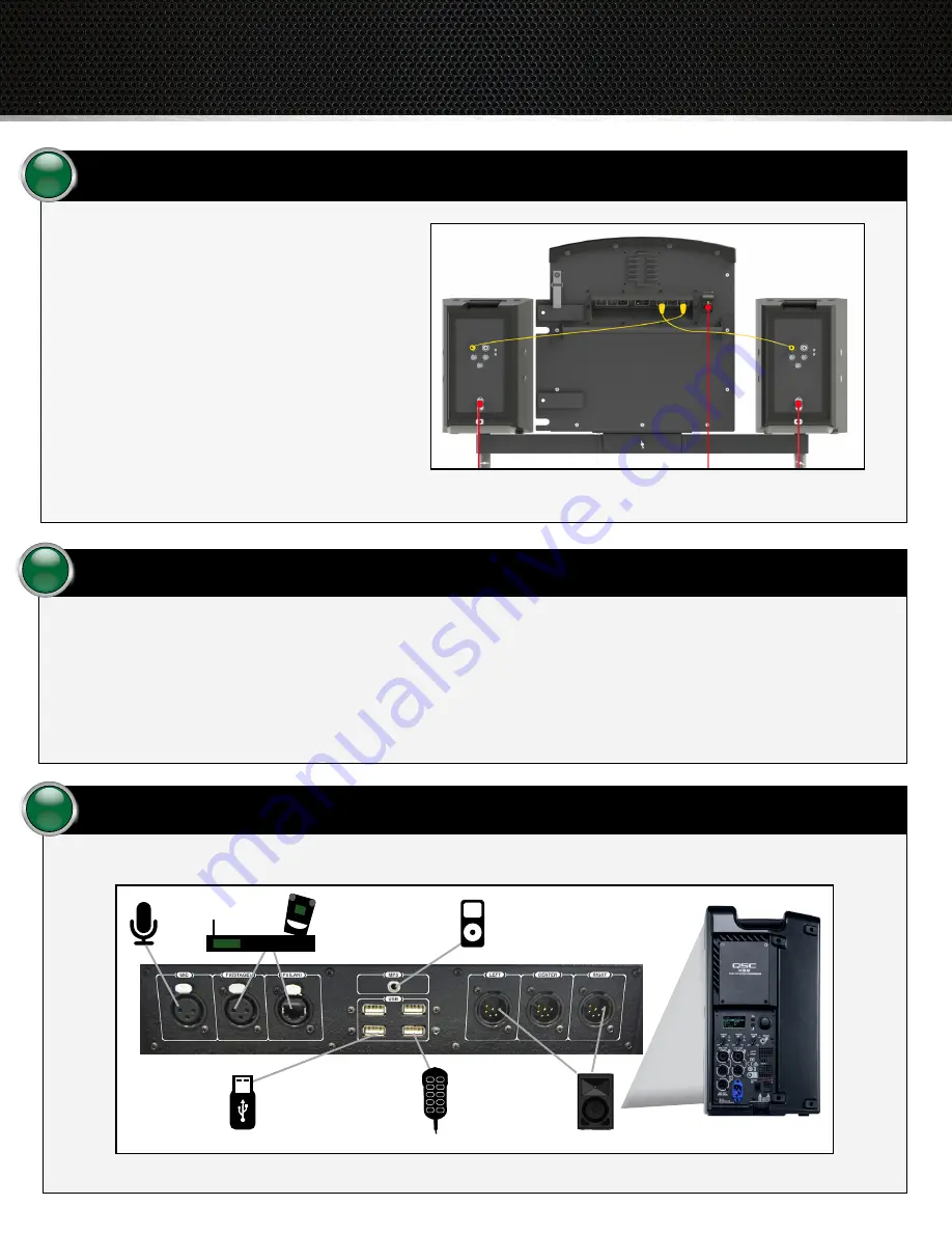
Connect the Control Unit’s power cable and the two speakers’ power cables into a power strip. (The power cables are red in Figure 6). Then, 
connect the power strip (via extension cord if necessary) to a 120 Volt 15 Amp power source. 

Note

:  

If you are using an optional Tempest FX system with Tempo Go, CoachComm recommends that you power on your FX system before 
powering on your Tempo Go Control Unit and speakers. See Step 8 on the following page for more information about FX setup.

CAUTION:


Protect the power cords from foot or vehicle traffic. Do not allow Tempo Go cords to become pinched or crimped, particularly where 
plugs enter power receptacles and/or where they exit from the unit. 

5

Test your equipment.

6

Test your microphone, portable music player, and any other audio devices that are connected through the system. 

Figure 7: Control Unit Connections and Speaker Rear I/O Panel

Mic

Speakers

Tempest

®

 FX 

System

Portable 

Music Player

Control Unit Back Panel

Tempo USB

Remote 

(available USB port)

External USB Drive with 

Tempo Script (available 

USB port)

Speaker Rear Panel

4

Connect the 6-pin ends of the two audio cables to 
the “LEFT” and “RIGHT” ports on the rear of the 
Control Unit. Then, connect the 3-pin ends to the 
“MIC/LINE IN A” ports on the rear of each speaker. 
(The audio cables are yellow in Figure 6.)

Verify that the speakers’ settings are as follows:

• 

Gain A: 

0 dB 

• 

Gain B: 

0 dB

Note: 


See Step 8 on the following page to 
connect an optional Tempest

®

 FX system. 

Connect the audio cables.

Figure 6: Tempo Go Audio Cables (Yellow) and Power Cables (Red)

Summary of Contents for Tempo Go

Page 1: ...ds Avoid deploying the system when wind speed exceeds 20 mph Failure to heed these recommendations may result in system damage and personal injury For setup and operation assistance contact CoachComm Customer Support CoachComm LLC Voice 800 749 2761 or 334 321 2300 Fax 866 793 SERV 7378 or 334 821 0397 customer service coachcomm com Assemble the tripods 1 Fully extend the two tripods Full extensio...

Page 2: ...ount the Control Unit and speakers Place the Tempo Control Unit onto the mounting bracket Be sure to align the holes in the Control Unit mount and bracket Use one of the provided pins to secure it in place as shown in Figure 4 Place the two speakers atop the bracket posts on each side of the Control Unit as shown in Figure 5 3 Figure 4 Control Unit Secured to Mounting Bracket Figure 5 Speakers Pla...

Page 3: ...eceptacles and or where they exit from the unit 5 Test your equipment 6 Test your microphone portable music player and any other audio devices that are connected through the system Figure 7 Control Unit Connections and Speaker Rear I O Panel Mic Speakers Tempest FX System Portable Music Player Control Unit Back Panel Tempo USB Remote available USB port External USB Drive with Tempo Script availabl...

Page 4: ...oachComm Tempo and Tempest are registered trademarks of CoachComm LLC All other trademarks are property of their respective owners Document Reference D0000422_B Use your software 7 Download the Tempo software on your PC to create a practice script Save the script from your PC to a USB flash drive For more information on creating and exporting a script refer to the Tempo Go Operating Manual When pr...

Reviews: