background image


5. RDU (Remote Display Unit) 

 
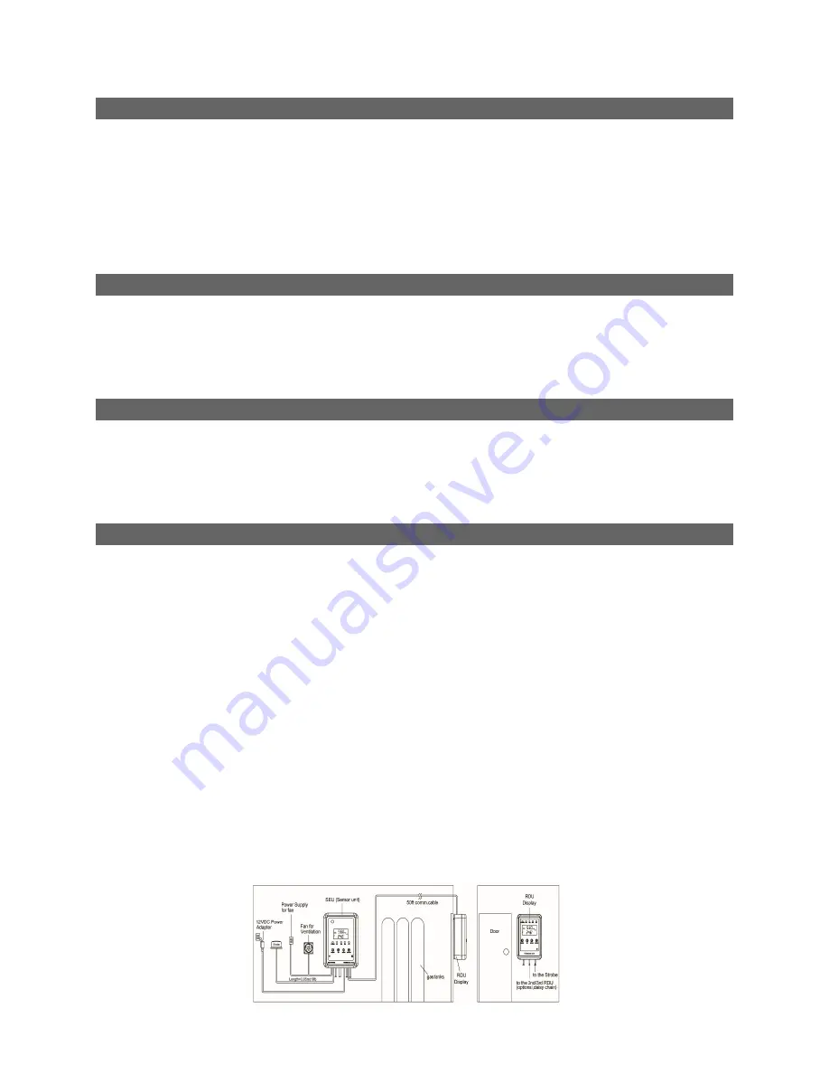
The RDU displays the data from the SEU and provides visual and audible indication that the SEU 
is in alarm status.    The RDU is NOT an external/second sensor.    The RDU is connected to the 
SEU with a CAT5 cable. A 25-foot CAT5 cable is provided. Users can source additional cable 
lengths as needed. The RDU should be placed where it can be conveniently observed (eye level) 
before entering the room/space.     
The “DIAG” function can test the communication between the SEU and RDU (see 9.1). Resetting 
the RAD-0102-6 CO2 Monitor is only available from SEU. 
 

6. Strobes 

 
The RAD-0102-6 can be equipped with strobes for additional visual alarms. Using CAT5 cables, 
connect the strobes to the correct RJ45 ports on the SEU and RDU. If CO2 levels exceed AL2, 
the strobe will flash. If the CO2 level exceeds AL3, the strobe tempo increases.   
Please visit www.CO2Meter.com for strobe package. Part Number: CM-1026. 
 

7. Power 

 
The RAD-1020-6 comes pre-wired with a 12V power supply that plugs in to a wall outlet. The 
12V power supply can be removed and 24V DC can be wired directly to the device through the 
terminal block. Please use a 24V DC power converter to properly convert your AC power 
source.   
 

8. Installation Instructions 

Please carefully remove all items from the package and follow the Step-by-Step Installation 
Instructions: 
1. Choose a suitable location to install the SEU. Fix the panel holder on the wall with the four 

screws. Install the SEU 18 inches from floor and close to the CO2 source.   

2. Put the SEU on the panel holder, making sure that they are connected tightly. 
3. Fix another panel holder in a suitable location outside the monitored space at eye level. Place 

the RDU onto panel holder, and stick the warning signs next to RDU.     

4. Route the 25-foot CAT5 cable between the SEU and RDU. CAT5 cable can be run through the 

wall/conduit or fixed to the wall using cable clips. Plug the CAT5 cable into the designated ports. 
Communication between the SEU and RDU is complete.       

5. The RAD-0102-6 has 3 relay outputs connected to the programmed alarm settings. All relays 

are normally open/closed dry contacts.    Any of the relays can be used to control an external 
device (fan, HVAC system, etc.) or can be wired to the fire alarm panel directly. The relays will 
trigger when the CO2 concentration exceeds the programmed alarm level.     

6. When the power has been connected, The SEU and the RDU will begin to work.   
7. Please use the “DIAG“ function to verify the communication between SEU and RDU, the five 

LED’s will blink and buzzer will sound on SEU & RDU, after that the communication is ready. 
The units will display the same information. 


Summary of Contents for RAD-0102-6

Page 1: ... monitoring RAD 0102 6 CO2 Monitor is cost effective and includes these features 1 Multiple RDU s can be connected for additional alarm points 2 Large digital LCD display clearly indicates the ambient CO2 concentration relative humidity and temperature 3 3 independent relay outputs can automatically control vent fan or be wired to the fire alarm panel 4 Audible and visual alarm indications 5 Autom...

Page 2: ...N 4 20mA Out O Battery P DC Power Supply Q RDU Cable RJ45 R Relay 3 AL3 S Relay 2 AL2 T Relay 1 AL1 U Strobe Cable RJ45 V Panel Holder RDU Remote Display Unit A Power Green LED B AL1 Red 1 LED C AL2 Red 2 LED D AL3 Red 3 LED E Fault Yellow LED F LCD display G Mode Button H UP Button I Down Button J Enter Button K Buzzer L Strobe Cable RJ45 M Output Cable to RDU RJ45 N Input Cable from SEU RDU RJ45...

Page 3: ...The AL2 Red 2 LED will flash The buzzer will sound see 9 3 AL3 3rd CO2 Alarm Level Relay 3 will be triggered when CO2 concentration exceeds the 3rd alarm level Preset at 30 000ppm The AL2 Red 2 LED AL3 Red3 LED and Fault LED will flash The buzzer will sound This status will be latched see 9 4 CALI Calibration To calibrate the CO2 sensor when the accuracy deviates from the actual CO2 concentration ...

Page 4: ... Relay 2 will be triggered When the CO2 value drops below the AL2 CO2 level AL2 Red 2 LED will stop blinking the buzzer will stop and Relay 2 will be inactive If the CO2 concentration continues to rise and exceeds the AL3 CO2 level AL2 Red 2 LED and AL3 Red 3 LED will flash together The tempo of the flashing and buzzer will increase RAD 0102 6 will latch after this event When the CO2 value drops b...

Page 5: ...nstructions Please carefully remove all items from the package and follow the Step by Step Installation Instructions 1 Choose a suitable location to install the SEU Fix the panel holder on the wall with the four screws Install the SEU 18 inches from floor and close to the CO2 source 2 Put the SEU on the panel holder making sure that they are connected tightly 3 Fix another panel holder in a suitab...

Page 6: ...Alarm Level Lock Lock Unlock User cannot adjust the alarm levels when Locked Default is Lock 1 Press Up Enter button for 10 seconds 2 Change to Advance Mode by press Mode and choose Alm Mode 3 Press Up Down to set Alm level Lock or Unlk 4 Press Enter to Save 9 3 Barometric compensation On Off Default is On Unit automatically compensates for barometric pressure altitude 1 Press Up Enter button for ...

Page 7: ...nit ºC ºF Press Up to switch between ºC and ºF Select Barometric hPa inHg Press Down to switch between hPa and inHg 10 1 Using the DIAG function Will test the communication link from SEU RDU 1 Press Mode until the DIAG icon flashes 2 Press Enter the SEU s five LEDs will blink and the buzzer will sound 3 The RDU s five LEDs will blink and buzzer will sound simultaneously 10 2 Checking the AL1 CO2 T...

Page 8: ...0 alarm level 4 Press Enter again to save the setting after selection or press Mode to quit the setting 10 4 Setting the AL3 3rd CO2 Alarm Level parameter User configurable 1 Press Mode until the AL3 CO2 icon flashes 2 Press Enter the AL3 icon shows on LCD Default AL3 3 0 3 Press Up Down to go through 2 0 2 5 3 0 3 5 4 0 alarm level 4 Press Enter again to save the setting after selection or press ...

Page 9: ...opening on the top left hand corner 2 Open the gas regulator Flow rate should be between 0 15 0 50 liters per minute 3 Wait until the CO2 reading on the SEU settles consistently at or near 0ppm CO2 4 Press the Mode button 5 times the CO2 and CALI icon will start flashing on the SEU 5 Press Enter to view the calibration settings The SEU screen will now display a flashing ZEro and CO2 6 Press Enter ...

Page 10: ...e able to remain exposed without risk of electric shock 4 Please take care of cable connection between SEU and RDU Make sure the cable from SEU Output RDU port is connected to the RDU INPUT SEU RDU port 5 The dry contact relays do not provide power to external devices like a ventilation fan If there is no power supply to the fan the relay will not work This may result in potential danger with high...

Page 11: ... Accuracy 1 5 C 2 7 F when CO2 level is below first alarm level Response Time 20 30 minutes case must equalize with environment Operating Conditions Temperature 0 C to 50 C 32 F to 122 F Humidity Range 0 95 RH non condensing Storage Conditions Storage Temperature 20 C to 60 C 4 F to 140 F Power Supply Power Supply DC 9 32VDC 12 32VDC recommended 2A AC adapter Input 100 240 VAC 50 60Hz 0 6A Output ...

Page 12: ...5 flash Fault LED blink Power on again or press reset button if the Er5 always appear please contact CO2Meter 3 Er7 Internal Data Transmission Error Er7 flash Fault LED blink Er7 flash Fault LED Blink Check the RJ45 plug is connected into the INPUT port of RDU if the Er7 displays on the RDU only Press reset button on SEU or power cycle the unit 15 Support Warranty Contact us We re here to help If ...

Reviews: