


C11G (Rev. 8.2) User Manual
Revision: 01/27/2010 http://cnc4pc.com/TechDocs/C11GR8_2_User_Manual.pdf 12/21
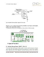
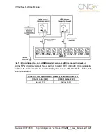
7. Wiring diagrams
While this board supports only TTL +5VDC signals, different kind of sensors,
switches using different voltages can be connected using the diagrams that follow:
Note:
The below wiring diagrams are an example, any input can be used for the connections.
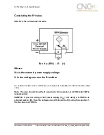
Note.
The bellow wiring diagrams require setting the inputs to use pull-down
resistor.
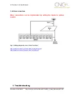
7.1 Connecting Switches or push button.
Fig. 7 Wiring diagram to connect switches.


