CNC4PC C11G User Manual Download Page 10

C11G (Rev.8.2) User Manual 


Revision: 01/27/2010       http://cnc4pc.com/TechDocs/C11GR8_2_User_Manual.pdf 10/21 


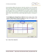
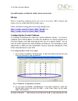
After configuring the Mach, these steps should be followed. 
 

Step 1.  

Ensure that all external power sources are set to 

OFF. 


Step 2.

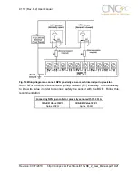
 Connect the power supply to the Power Inputs Connectors (X1). 


Step 3. 

Turn on the external supplies 

Step 4.

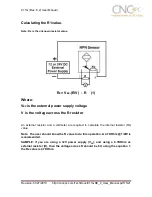
 Connect a voltmeter in the analog outputs connectors (X2) and make and 

fine tune this output: 

Make  sure  that  when  you  reach  the  max 
speed in the control software you get 10VDC 
out  (X2).    This  voltage  can  vary  depending 
on  many  things,  including  the  electrical 
properties  of  parallel  port  or  breakout  board 
you  are  using,  the  length  of  the  step  pulse 
your software is delivering, and the normal hi 
or  low  status  of  your  step  pin.  Play  with  the 
pot, hi/low status of the pin, and pulse length 
to fine tune the output voltage. 


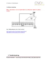
6.3  Electromechanical relays.  (pins 1 and 16) 

Mechanical  relays  are  very  flexible  because  they  can  be  used  for  AC  or  DC  and 
come with NO and NC (Normally Open and Normally Closed) positions. Relay are 
independents, one reacts to Pin 1 and the other one to Pin16 and that both can be 
used at the same time. The relay specification are showed in the below table. 
 

ELECTROMECHANICAL RELAYS SPECIFICACTIONS 

Maximun Current (AC) 

7A@240VAC; 10A@125VAC 

Maximun Current (DC) 

15A@524VDC; 10A@28VDC 


Table 2. Electromechanical Relays Specifications. 


Summary of Contents for C11G

Page 1: ...best input configuration for your application Buffered inputs and outputs Outputs are buffered through the use of high speed and high current buffers allowing the card to output the signals without us...

Page 2: ...s or limit switches you can set It to be 5VDC External Enable Pin EN The board has a pin that allows you to enable disable all the outputs at once The board requires 5vdc in the EN pin If it is not pr...

Page 3: ...m off state voltaje 0 44 V Maximum operation frequency 4 MHz Typical signal delay 10 nS Time of transition to high impedance state 12 nS Time passed since a low in the ENABLE input is detected and the...

Page 4: ...buffer 4 2 Outputs 1 14 16 and 17 simplified functional block diagram Fig 2 Simplified functional block diagram for the outputs 1 14 16 and 17 Note Internal Enable External Enable Pin AND SCHP OR Bypa...

Page 5: ...e jumper in the appropriate position The input pins can be set to be pulled up or down with a 4 7Kohm resistor 1 2 PULL UP 2 3 PULL DOWN 5 Special Functions 5 1 Safety Charge Pump SCHP Pin 17 This boa...

Page 6: ...ne of the pins This card lets you use this signal to work as an On Off switch for your system enabling a powerful safety system for your equipment If you ever had windows crash on you then this card i...

Page 7: ...indle with step and direction signals as if it was an axis motor It converts the step signal into an analog 0 10VDC A Variable Frequency Drive or Inverter works by modifying the frequency for AC motor...

Page 8: ...figure your control software to control the spindle as if it was an angular axis This card requires a 25 KHz input signal in the pin 14 to deliver 10VDC So you have to set the speed of the motor spind...

Page 9: ...For Acceleration choose the acceleration that you feel comfortable with Start slow increase acceleration as you test your system Under Step Pulse length use a number from 3 to 5 but start with 3 This...

Page 10: ...l properties of parallel port or breakout board you are using the length of the step pulse your software is delivering and the normal hi or low status of your step pin Play with the pot hi low status...

Page 11: ...n This feature has been added to externally control the status of the outputs An external switch or a Safety Charge Pump can be added to provide the enabling signal When the enable signal is not prese...

Page 12: ...ls different kind of sensors switches using different voltages can be connected using the diagrams that follow Note The below wiring diagrams are an example any input can be used for the connections N...

Page 13: ...df 13 21 7 2Connecting NPN sensors Fig 8 Wiring diagram to connect NPN open collector proximity sensors Fig 9 Wiring diagram to connect in parallel NPN open collector proximity sensors Connecting NPN...

Page 14: ...proximity sensors with internal pull up resistor Some NPN proximity sensor has a pull up resistor R1 internally It is necessary to know its value in order to connect safely the sensor with the BOB Fo...

Page 15: ...supply voltage V is the voltage across the R resistor An external resistor and a voltmeter are required to calculate the internal resistor Rx value Note The user should know the R value to do this ope...

Page 16: ...27 2010 http cnc4pc com TechDocs C11GR8_2_User_Manual pdf 16 21 7 3 Connecting PNP sensors Fig 11 Wiring diagram to connect PNP proximity sensors Connecting PNP proximity sensor with the C11G R Value...

Page 17: ...User_Manual pdf 17 21 7 4 Other connection Other connections can be implemented by setting the inputs to pull up resistor Fig 12 Wiring diagram to do an Auto Tool Zero http cnc4pc com Tech_Docs E_STOP...

Page 18: ...ke the waveform it is getting Some breakout boards could invert the signals or modify the pulse width Changing the active low status of the pin used also inverts the waveform Play with the active low...

Page 19: ...ck if the parallel port is well connected to the PC SYMPTOM 3 THERE IS NOISE IN THE SYSTEM OR THE MOTORS DO NOT MOVE SMOOTHLY POSSIBLE CAUSE POSSIBLE SOLUTIONS The board could be underpowered Make sur...

Page 20: ...ould be a way of figuring out if this is the case There could be a problem with the parallel cable or parallel port Test this with a different PC or parallel port SYMPTOM 5 THE ANALOG OUTPUT DOES NOT...

Page 21: ...ion CNC machines could be dangerous machines DUNCAN USA LLC or Arturo Duncan are not liable for any accidents resulting from the improper use of these devices The C11G is not fail safe device and it s...

Reviews: