background image

XNET Network Dome Camera Installation Manual 

6 /

 22 

2

2

.

.

3

3

.

.


H

H

a

a

r

r

d

d

w

w

a

a

r

r

e

e


D

D

e

e

s

s

i

i

g

g

n

n

a

a

t

t

i

i

o

o

n

n


2

2

.

.

3

3

.

.

1

1

.

.


S

S

w

w

i

i

t

t

c

c

h

h


a

a

n

n

d

d


C

C

o

o

n

n

t

t

r

r

o

o

l

l

s

s


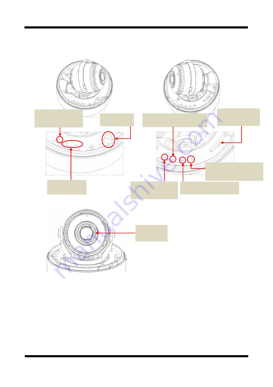
This shows Camera module inside the dome cover.     


STATUS LED 


PWR LED : 

Red light indicates that 12V DC power is connected.


EVENT LED : 

Green light indicates that Alarm Out signal is turned on. 


SYSTEM LED : The system operates normally when the Green LED blinks 


LINK LED : Red light indicates 

that the network is properly connected.


ACT LED : 

Green light indicates that the XNET system connected to 100Mbps LAN. This green lamp 

will blink If the system receives data.


Analog Video 
Output


EVENT LED


EVENT Alarm Out 

Signal is turned on. 


SYSTEM LED 

The camera at the end of boot


PWR LED 

Power is connected indicates 

SD CARD SLOT 

For  Mounting  the  SD 
Card Slot. 

Factory Reset button 

Recalls factory default 
configurations 

ACT, LINK LED 

Network status LED 


EASY-SWITCH(Auto Focus) 
Adjust automatically   
the focus of the camera 

Mega Pixel 

Motorize Lens 

Summary of Contents for XNET NDE5055MF

Page 1: ...XNET Network Dome Camera Installation Manual Ver 1 2 XNET Network Dome Camera NDE5055MF Installation Manual...

Page 2: ...em with the product Contact the store or the manufacturer before disassembling the product for alteration or repair XNET is a trademark of CNB Technology Inc This product complies for CE Europe and FC...

Page 3: ...signation 6 2 3 1 Switch and Controls 6 2 3 2 Connecting Cables 7 2 3 3 Connecting to Alarm Devices 9 3 Software Installation 10 3 1 Installing XNET 10 3 1 1 Installation 10 3 1 2 Cable Connection 11...

Page 4: ...munication Bi directional voice communication between Client s PC and XNET Smart Event feature On the top of motion detection and sensor alarm feature pre and post alarm feature allows automated surve...

Page 5: ...OUTPUT 12VDC 2A GUIDE PATTERN Guide Pattern CD Software and User s manual DC JACK DC CONNECTOR CVBS JACK Connect the Power Adaptor DC jack Connect the DC jack Connector CVBS JACK Accessory SCREW 3EA...

Page 6: ...ally when the Green LED blinks LINK LED Red light indicates that the network is properly connected ACT LED Green light indicates that the XNET system connected to 100Mbps LAN This green lamp will blin...

Page 7: ...utput Audio Connection MIC Line Input Mono Connects to auxiliary Audio device or microphone Line Output Mono Audio signal output to a Power Amplified device or Speaker This can be used to listen to th...

Page 8: ...s and hold for more than 3 seconds while power is on to recall factory default settings Network Cable This Ethernet terminal connects to 100Mbps LAN through an RJ 45 cable When optional PoE is used th...

Page 9: ...igure 2 5 NC or NO of sensor input can be selected at Menu screen Alarm Sensor device requires a separate power source Alarm in Alarm in Photo Coupler Sensor Device Signal 5 30VDC GND Adaptor Internal...

Page 10: ...e store Our homepage is http www cnbtec com 3 3 1 1 I In ns st ta al ll li in ng g X XN NE ET T 3 3 1 1 1 1 I In ns st ta al ll la at ti io on n Mount the Camera to a ceiling or a wall Make sure the b...

Page 11: ...23 100 after connecting XNET camera to your PC directly This process approximately takes 20 30 seconds 2 Please follow the direction to modify PC s network configuration Windows Start Control Panel Ne...

Page 12: ...se insert the Setup CD into your CD ROM drive and then please setup IPInstaller program 4 Please click Next button when the Setup screen appear 5 Please click Install button to begin the Installation...

Page 13: ...XNET Network Dome Camera Installation Manual 13 22 7 XNET IP Installer program is automatically launched like below right after the program installation Please double click XNET camera on the list...

Page 14: ...et Explorer will prompt you to install ActiveX In order to view video you must accept the ActiveX download NOTE Please select Setting menu for XNET camera configuration If the login prompt appears ple...

Page 15: ...ra and PC to a router using LAN cables like below NOTE If DHCP server is enabled at your router XNET camera automatically receives an IP address from your router Otherwise XNET camera s IP address wil...

Page 16: ...nstaller software provided in the Installation CD included in the package and also available to download from our website http www cnbtec com will configure IP address easily If your network have a DH...

Page 17: ...nd click Set IP Address button to bring up the following box in Figure 3 2 Figure 3 2 IP Address box 3 When you enter the IP address and click Set button the box shown in Figure 3 3 will appear Figure...

Page 18: ...respectively If you want to use a different HTTP port number from the default value simply put a colon and port number at the end of the IP address For example enter the following address when changin...

Page 19: ...XNET Network Dome Camera Installation Manual 19 22 4 4 2 2 W We eb b V Vi ie ew we er r P Pa ag ge e Web viewer page consists of Video monitor screen and menu option buttons Figure 4 2 Web Viewer Page...

Page 20: ...ner s Manual for detail Motorize Live View Main Stream When this box is checked Main Stream Video is displayed Dual Stream When this box is checked Dual Stream Video is displayed Dual Codec needs to b...

Page 21: ...pression level setting Configurable White Balance Brightness Saturation Sharpness DNR 3DNR BLC EXPOSURE Intelligent Audio Two way full duplex G 711 Network Protocol IPv4 HTTP TCP RTSP RTP UDP SMTP FTP...

Page 22: ...tion Manual 22 22 Pan Tilt Horizontal 4 Axis Movement for Free Lens Rotation Power 24VAC 24 28V 12VDC 11 15V Dual Voltage Maximum Motorize on FAN on DC12V 4 5W AC24V 375mA Dimensions Weight Net 119 1...

Reviews: