


Network Weatherproof Camera Installation Manual
7
/ 20
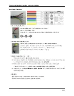
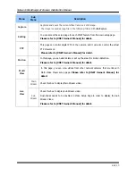
2.3.2 Camera Module – Rear
As shown in the picture above, open up the rear cap by undoing the four screws on the corners.
Main body
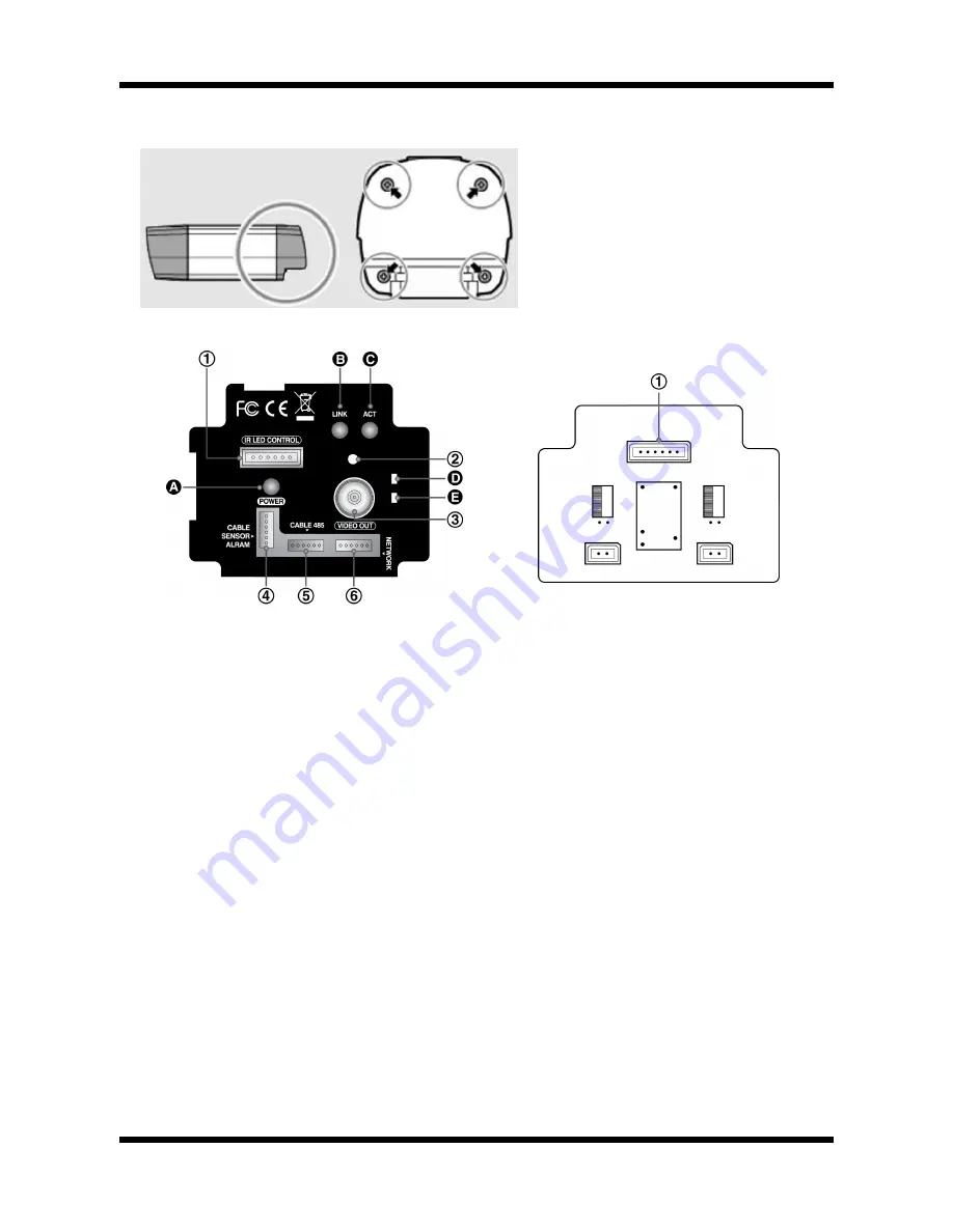
Rear body
①
Illuminator Control Connector
: controls the IR LED units
②
Factory Reset Button :
Press and hold for more than 3 seconds while power is on to recall factory
default settings
③
Video Out Jack :
Analog Video output. Use this output to monitor the analog video signal during
installation.
(Enable Video Out at menu screen to turn this video on)
④
CABLE IN 1 ( Alarm / Sensor / Power IN / Video out ) – [ Class 1 Only ]
Alarm Input/ Output, DC12V Input, and Analog Video Output
⑤
CABLE IN 2 ( RS485/Power IN/Video out ) – [ Class 2 Only ]
This connects to control P/T(Pan/Tilt) device by RS485 interface
⑥
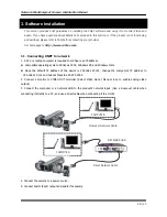
Network Input Cable:
Ethernet Input. Connects to a 10Mbps or 100Mbps LAN via waterproof RJ45
Connector.
Ⓐ
Power LED :
Lights up
Red when 12V DC power is connected.
Ⓑ
Link LED :
Lights up Yellow when the network is properly connected.
Ⓒ
ACT LED :
Lights up Green when the XNET is connected to
100Mbps LAN. Will not light up at 10Mbps
LAN. This will also blink green when there is a network collision.
Ⓓ
SYSTEM LED :
Blinks Green to indicate a normal operation.
Ⓔ
EVENT LED :
Lights up Green when ALRAM OUT is activated.


