background image

6

10001921 REV AC

   July 2019

INSTALLATION

UNPACKING INFORMATION

When received, the hoist should be carefully inspected for damage 

which may have occurred during shipment or handling. Check  

the hoist frame for dents or cracks, the external cords for damaged 

or cut insulation, the control station for cut or damaged enclosure, 

and the load chain for nicks and gouges. If shipping damage has 

occurred, refer to the packing list envelope on the carton for  

claim procedure. 

Before using the hoist, make sure the voltage change board is 

connected for the intended power supply the hoist is to be operated. 

NOTE: See Electrical Installation instructions. 

INSTALLING THE SUSPENSION 

(If Applicable)

A. SINGLE REEVED UNITS:

Remove the hook suspension and (2) suspension screws from the 

packaging. Place the suspension assembly into the recess on top  

of the hoist so that the adapter body follows the contour of the hoist. 

Insert the suspension screws through the holes in the adapter and 

hand thread these into the self-locking nuts enclosed in the hoist. 

The screws will turn freely into the nuts until the last 1/4" (6.35 mm) 

of travel, during which the resistance of the nut locking collar will  

be encountered. 

DO NOT apply any type of lubricant to the 

threads of these screws.

USE OF IMPACT TOOLS (ELECTRIC OR PNEUMATIC) MAY 

CAUSE PREMATURE FAILURE OF ATTACHING HARDWARE.

Securely tighten the screws to the recommended seating torque  

using a 12 point socket 3/8" for Models B, C, and F and 1/2" for 

Models J, L, LL, R and RR and 3/16" hex bit socket  

for Model RRS." 

For Model RRS: 

Remove the hook suspension, screw and locknut 

from the packaging. Slide the suspension assembly into the channel 

in the top of the hoist. Insert the locknut into the hex recess on 

the side of the suspension riser, insert the screw through opposite 

side and hand thread the screw into the self-locking nut. Tighten to 

recommended torque.

B. DOUBLE REEVED UNITS: 

Remove the hook suspension, (2) suspension screws, (1) dead end 

pin, (1) washer, and (1) cotter pin from the packaging. It should be 

noted that the suspension includes a dead end bolt and block for 

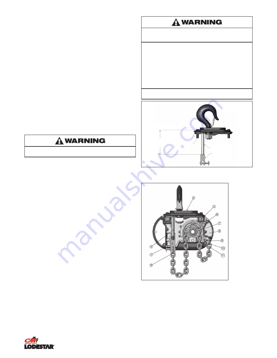
supporting the dead end of the load chain as shown in Figure 3. 

Place the suspension assembly into the recess on top of the hoist. 

The dead end block should project through the bottom of the hoist 

with the pin hole and slot aligned to the underside of the hoist as 

shown in Figure 4. 

If these are not aligned as shown, lift the head of the bolt from  

the hex recess in the adapter and turn the bolt and block assembly 

and reseat the bolt head to obtain the proper alignment. 

DO NOT 

change the position of the dead end block on the bolt to attain  

this alignment. 

Check the position of the pin hole in the dead end block to make 

sure it has not been disturbed from its factory setting. The distance 

from the top of the pin hole to the bottom of the hoist should not 

exceed 7/16" (11.11 mm) for the Models R and RR. If the distance  

is not correct, adjust the position of the dead end block to obtain  

the proper distance (see Figure 3). 

Now, insert the suspension screws through the holes in the adapter 

and hand thread these into the self-locking nuts enclosed in the 

hoist frame. 

DO NOT apply any type of lubricant to the threads of 

these screws.

 The screws will turn freely into the nut until the last  

1/4" (6.35mm) of travel during which the resistance of the nut 

locking collar will be encountered. Securely tighten the screws to the 

recommended seating torque (see Table 11) using a 12 point socket 

3/8" for Models B, C & F and 1/2" for Models J, L, LL, R and RR. 

The dead end of the load chain is temporarily positioned (a few 

links from the end) by a wire tie. 

DO NOT remove this tie before 

attaching the chain to the dead end block

Using other than CM supplied high strength suspension screws to 

attach the suspension adapter to the hoist may cause the screws 

to break and allow the hoist and load to fall.

TO AVOID INJURY:

Use only the CM supplied suspension screws to attach the 

suspension to the hoist and hand torque these screws to the 

recommended seating torque as specified in tables 11a, 11b,  

11c, & 11d.

DO NOT apply any type of lubricant to the threads of these 

screws. Lubricating the threads will reduce the effort to seat 

the screws and as a result, tightening the screws to the above 

recommended torque may break the screw, damage the 

suspension adapter, strip the nuts and/or damage the hoist frame.

SUSPENSION BOLT SHOULD BE REPLACED ANY TIME THE 

SUSPENSION IS REMOVED FROM THE HOIST.

UNDER SIDE 

OF SUSPENSION 

ADAPTER FLANGE

DEAD END BOLT

DEAD END BLOCK

5.45in

(138.43mm)

Models R & RR

Figure 3. Double Reeved Suspension Assembly


Figure 4. Suspension Components 

(Chain Plate not shown for clarity.)

1.  Dead end block 

2.  Suspension assembly 

3.  Suspension self-locking nut  

4.  Dead end bolt 

5.  Dead end link 

6.  Chain guide 

7. Lift-wheel 


8.  Gear housing 

9.  Loose end screw  

10.  Loose end link  

11.  Loose end

Summary of Contents for Lodestar B

Page 1: ... or property damage That risk is greatly increased if proper instructions and warnings are not followed Before using this hoist each operator should become thoroughly familiar with all warnings instructions and recommendations in this manual Retain this manual for future reference and use Forward this manual to operator Failure to operate equipment as directed in manual may cause injury ELECTRIC C...

Page 2: ...TION FOR THE NAME OF THE NEAREST PARTS OR SERVICE CENTER VISIT OUR WEB SITE WWW CMWORKS COM OR CALL OUR CUSTOMER SERVICE DEPARTMENT AT 800 888 0985 AN ELECTRONIC COPY OF THIS MANUAL AND THE CM HOIST PARTS AND SERVICES LIST IS AVAILABLE AT http www cm et com products aspx id 23221 Follow all instructions and warning for inspecting maintaining and operating this hoist WARNING ...

Page 3: ...ation 3 Use hook latches Latches are to retain slings chains etc under slack conditions only 4 Make sure the hook latches are closed and not supporting any parts of the load 5 Make sure the load is free to move and will clear all obstructions 6 Avoid swinging the load or hook 7 Make sure hook travel is in the same direction as shown on the controls 8 Inspect the hoist regularly replace damaged or ...

Page 4: ...5 Clutch Adjustment 15 16 Limit Switches Models B F 17 17 Rotatable Limit Switches Models B F 17 18 Limit Switches Models J RR 17 19 Rotatable Limit Switches Models J RR 17 FOREWORD This manual contains important information to help you properly install operate and maintain your hoist for maximum performance economy and safety Please study its contents thoroughly before putting your hoist into ope...

Page 5: ...630 138 63 Hoist with cords only less chain and suspension Net Weights are approximate and will vary depending on lift height and options selected Please contact factory for actual hoist weight LODESTAR D8 According to VPLT SR2 0 and SQP2 D8 Plus chain hoists are used to lift loads during set up and have the special characteristic of being able to hold loads at rest above people without using a se...

Page 6: ...derside of the hoist as shown in Figure 4 If these are not aligned as shown lift the head of the bolt from the hex recess in the adapter and turn the bolt and block assembly and reseat the bolt head to obtain the proper alignment DO NOT change the position of the dead end block on the bolt to attain this alignment Check the position of the pin hole in the dead end block to make sure it has not bee...

Page 7: ...e placed on the small end of the pin The small end of the pin is the end opposite the end on which the 3 grooves are visible Place the hook block in the V Block and drive the pin out using the drift and a hammer or slow acting press To re install the pin the parts must be arranged the same as they were when the pin was removed To do this use the small end of the pin as a gage First check the holes...

Page 8: ...ate on 460 3 60 or 380 3 50 or 415 3 50 VOLTAGE CHANGE BOARD A voltage change board is provided to easily and quickly change from 460 to 230 or 380 to 220 or 415 to 220 volt operation The voltage change board shown in Figure 9 is located in the hoist as shown in Figure 10 The voltage change board is color coded to indicate high and low voltage connections Connecting the 9 and 12 pin plugs into the...

Page 9: ... components as well as heating of the wires and connectors in the circuit feeding the hoists Failure of the hoist to lift the load due to motor stalling Blowing of fuses or tripping of circuit breakers To avoid these low voltage problems the hoist must be connected to an electrical power supply system that complies with the National Electrical Code and applicable local codes This system must also ...

Page 10: ...of hoists refer to page 3 1 Permit only competent personnel to operate unit 2 When preparing to lift a load be sure that the attachments to the hook are firmly seated in hook saddle Avoid off center loading of any kind especially loading on the point of hook 3 Do not allow the load to bear against the hook latch The latch is to help maintain the hook in position while the chain is slack before tak...

Page 11: ...hey become unsafe Inspection intervals must be determined by the individual application and are based on the type of service to which the hoist will be subjected The type of service to which the hoist is subjected can be classified as Severe Normal Stand by Rental or Out of Service Stand by Service Hoist operates 25 or fewer days a year but at least once Rental Service Hoist is operated on an irre...

Page 12: ... of loose screws bolts or nuts Evidence of worn corroded cracked or distorted hook block body suspension screws gears bearings chain dead end and chain pin Evidence of damage or excessive wear of the lift wheel and hook block sheave chain pockets Link by link inspection of the chain for evidence of excessive interlink wear and damage Evidence of chain guide wear or damage where the chain enters th...

Page 13: ...2mm 91 23 1mm 1 48 37 7mm 75 18 8mm J JJ L LL 1 31 33 3mm 1 08 27 5mm 1 48 37 7mm 75 18 8mm R RR RRS 1 50 38 1mm 1 43 36 2mm 1 92 48 8mm 94 23 9mm INSPECTING THE LOAD CHAIN The chain must be inspected at regular intervals with a minimum of once annually As the frequency of use increases the time intervals between inspections must be reduced During inspection the chain link must be examined along t...

Page 14: ...TAIN THERE IS NO TWIST h For single reeved models attach the hook block to load chain and proceed to step K i For double reeved models run the hoist UP until only 914 4 mm 36 Inches of chain remains on dead end side This will minimize the chance of introducing a twist between hook block and hoist Allow the chain to hang free to remove twists j Using a wire as a starter insert the chain flat link f...

Page 15: ...oist is disconnected prior to any clutch adjustment TO AVOID INJURY The load limiter slip point should not exceed 1 6 times WLL of the unit MODELS B C F 1 Disconnect power to the unit 2 Remove access port plug located next to the External Chain Plate 3 Insert adjustment tool contact factory or CMCO post sales customer support for p n in access port 4 Align drive points of the adjustment tool with ...

Page 16: ...n Apply a light film of machine oil to the limit switch shaft threads at least once a year BEARINGS All bearings and bushings except the lower hook thrust bearing are pre lubricated and require no lubrication The lower hook thrust bearing should be lubricated at least once a month CHAIN GUIDES LIFTWHEEL AND LOWER SHEAVE WHEEL When the hoist is disassembled for inspection and or repair the chain gu...

Page 17: ...should be set between the top hook block and the bottom of the hoist CAUTION THE A DIMENSIONS SHOWN IN TABLE 8 ARE THE MINIMUM ALLOWED FOR SAFE OPERATION AND SHOULD NOT BE REDUCED 6 Reconnect hoist to power supply 7 Run hook to the desired upper position cautiously operating the hoist without a load 8 Disconnect hoist from power supply 9 Moving one travel nut toward the other increases hook travel...

Page 18: ...ising the hook about 2 feet 61cm then lower the hook by jogging cautiously until the lower limit switch stops downward motion The stopping point of the hook should be the desired lower position if not repeat the above instructions 12 Double check setting by raising the hook about 2 feet 61 cm and then run the hook into the lower limit with DOWN control held depressed 13 Fine adjustment of the lowe...

Page 19: ... or shorted coil winding armature binding G Check electrical continuity and connections Check that correct coil has been installed The coil for three phase dual voltage unit operates at 230 volts when the hoist is connected for either 230 volt or 460 volt operation Check brake adjustment as described on page 15 H Excessive load Mechanical load protector slipping H Reduce loading to the capacity li...

Page 20: ...ce or shield the hoist from radiation D Frequent starting or reversing D Avoid excessive inching jogging or plugging This type of operation drastically shortens the motor and contactor life and causes excessive brake wear E Phase failure or unbalanced current in the phase three phase unit only E See item 1B F Brake dragging F Check brake air gap as described on page 15 9 Hook fails to stop at eith...

Page 21: ...to 13 245 635 3 2 230 460 to 115 220 380 to 115 220 415 to 115 Pin 1 to 5 Pin 5 to 7 Pin 9 to 13 205 658 51 Table 10b Contactor Data Models Contactor Coil Voltage Nominal Current Amps D C Resistance Ohms B thru RRS 115 0 04 29 75 48 0 09 56 3 24 0 19 14 9 Resistance Values listed are nominal and they may vary slightly from component to component On dual voltage units 230 460 3 60 220 380 3 50 and ...

Page 22: ...0 5 6 6 8 Chain Stop Screw 1 4 20 Socket Head Cap Screw 3 16 Hex Driver 5 0 5 8 6 8 7 9 ClutchAdjustmentAccess Port Plug 1 4 NPTF Pipe Plug 1 4 Hex Driver 1 3 1 5 1 8 2 0 Table 11c Torque Specification Models J RR Fastener Fastener Description Tool Required Recommended Seating Torque ft lbf N m Motor Housing Gear Housing Back Frame Screws 5 16 18SocketHead CapScrew 1 4 HexDriver 14 2 15 0 19 2 20 ...

Page 23: ...23 10001921 REV AC July 2019 NOTES ...

Page 24: ... 2018 Columbus McKinnon Corporation All Rights Reserved 10001921 REV AC July 2019 ...

Reviews: