ELECTRIC VEHICLE - MOTOR
Motor Installation
16
8.
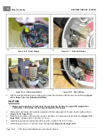
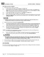
Install clamp (3) onto sensor wires (4) and secure with other screw (5) finger-tight. Ensure clamp (3) and wires (4)
are oriented as shown
. Tighten both screws (2 and 5) to 20 in·lb (2.2 N·m).
9.
Make sure the armature turns freely. If it does not turn freely, disassemble the motor to find the problem.
A
B
1
3
4
2
5
2
5
1
4
3
A. End View B. Side View
3066
Figure 16-20
Speed Sensor Clamp
MOTOR INSTALLATION
See General Warnings on page 1-1.
1.
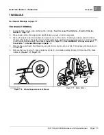
Clean the transaxle input shaft.
1.1.
Spray the input shaft thoroughly with CRC
®
Brakleen™ or equivalent brake cleaner degreaser.
1.2.
Wipe input shaft with a clean cloth.
1.3.
Inspect the grooves of the input shaft and remove any remaining debris.
1.4.
Repeat steps 1.1 through 1.3 until input shaft is clean.
2.
Lubricate the transaxle input shaft.
2.1.
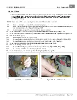
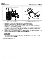
Squeeze approximately 1/2 inch (1.3 cm) of moly-teflon lubricant from tube onto a putty knife as shown
.
2.2.
Rotate wheels to rotate input shaft.
2.3.
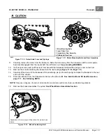
Apply motor coupling grease evenly to the rotating input shaft starting at approximately 1/8 inch (3.1
mm) from the end of the shaft and working back toward the transaxle (away from the end of the shaft)
.
2.4.
The grease should be evenly distributed in the grooves to a width of approximately 3/8 inch (9.5 mm).
2.5.
Use a flat screwdriver to clean the grease out of one of the grooves and allow air to escape when the
motor is pushed onto the input shaft.
2021 Carryall 300 Maintenance and Service Manual
Page 16-15
Summary of Contents for Carryall 300 2021
Page 2: ......
Page 16: ......
Page 551: ...80 2018 by Kohler Co All rights reserved KohlerEngines com 17 690 15 Rev...
Page 565: ...GASOLINE ENGINE HARNESS Wiring Diagrams Gasoline Engine Harness 26...
Page 566: ...Page intentionally left blank...
Page 567: ...GASOLINE KEY START MAIN HARNESS Wiring Diagrams Gasoline Key Start Main Harness 26...
Page 568: ...Page intentionally left blank...
Page 569: ...GASOLINE PEDAL START MAIN HARNESS Wiring Diagrams Gasoline Pedal Start Main Harness 26...
Page 570: ...Page intentionally left blank...
Page 571: ...GASOLINE INSTRUMENT PANEL HARNESS Wiring Diagrams Gasoline Instrument Panel Harness 26...
Page 572: ...Page intentionally left blank...
Page 573: ...GASOLINE FNR HARNESS Wiring Diagrams Gasoline FNR Harness 26...
Page 574: ...Page intentionally left blank...
Page 575: ...ELECTRIC MAIN HARNESS Wiring Diagrams Electric Main Harness 26...
Page 576: ...Page intentionally left blank...
Page 577: ...ELECTRIC INSTRUMENT PANEL HARNESS Wiring Diagrams Electric Instrument Panel Harness 26...
Page 578: ...Page intentionally left blank...
Page 579: ...ELECTRIC ACCESSORIES HARNESS Wiring Diagrams Electric Accessories Harness 26...
Page 580: ...Page intentionally left blank...
Page 588: ...NOTES...
Page 589: ...NOTES...
Page 590: ...NOTES...
Page 591: ...NOTES...
Page 592: ...NOTES...
Page 593: ...NOTES...
Page 594: ...NOTES...
Page 595: ......
Page 596: ......


