background image

V 1.0 

 12/03/2020 

 CLS-ENV-MU-20-0106 


12 


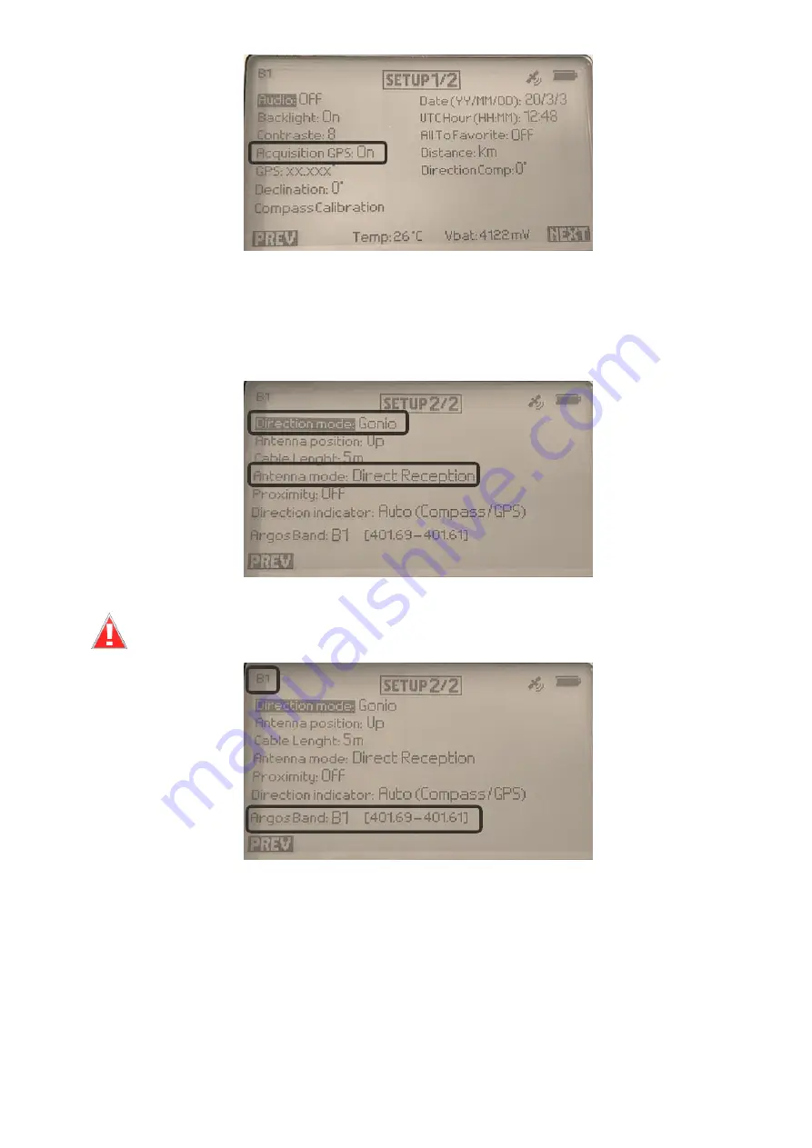
On the first screen of the SETUP menu, turn the Goniometer GPS ON by using the ARROW buttons and 
the Validation button. 

Go to the second screen of the SETUP menu by pressing the Navigation button under the "NEXT" label. 

Configure the direction and antenna mode parameters. 


Configure the Argos Band where your beacons(s) is/are transmitting. 


The Selected Band is always displayed on the top left corner in all screens 


Validate  the  setting  by  pressing  the  PREV  button  and  save  the  parameters  by  pressing  the 
Navigation button under the "YES" label. You will be taken back to the Screen 1 of the SETUP menu. 


Summary of Contents for ARGOS GONIO 2

Page 1: ...V 1 0 12 03 2020 CLS ENV MU 20 0106 1 GONIO 2...

Page 2: ...mong the favorite platforms 15 4 8 RECEPTION screen 15 4 9 The Argos platform recovery can start 16 5 Details of the screens 17 5 1 RECEPTION screen 17 5 2 FAVORITE screen 18 5 3 RECEIVING PLATFORMS s...

Page 3: ...ped with a GPS receiver the message is not encrypted and the latitude and longitude are coded simply In this case received Argos demodulated messages and Argos platform transmitter terminal PTT recept...

Page 4: ...ing antenna with 5 meter cables Gonio receiver Universal main power converter USB Cable Antenna mount BNC antenna In addition an USB key is also provided with the following documents and software Read...

Page 5: ...eceiver Front view RXG 134 or RXG 234 Top view GPS antenna Connector for USB and charger cable Receiving antenna connectors GPS antenna Navigation button Circular control pad Validation button Display...

Page 6: ...turn ON FAVORITES menu RECEIVING PTT menu OPTION menu RECEPTION screen FAVORITE menu RECEIVING PTT menu OPTIONS menu To go from one screen to another press the Navigation button under the NEXT or PREV...

Page 7: ...0 CLS ENV MU 20 0106 7 3 Antenna installation procedures 3 1 Goniometer antenna 1 Insert one of the two cables into the opening in the antenna mount 2 Then insert the second cable 3 Screw the mount in...

Page 8: ...6 8 You may also pass the cables through the hole on the side of the antenna mount 4 Connect both cables to the receiver Note The white pointer on the receiving antenna corresponds to the reference az...

Page 9: ...9 Important keep the antenna vertical and avoid touching it with your hands to prevent interference when the GONIO is receiving 3 2 BNC antenna Connect your BNC Argos antenna as shown in the figure b...

Page 10: ...from the favorite platforms list 6 check results displayed in the RECEPTION screen 7 platform recovery 4 1 Mount the antenna Mount and connect the Goniometer antenna or the BNC antenna according to s...

Page 11: ...ometer or BNC antenna GPS ON can be OFF ON Direction mode Gonio GPS Antenna mode Gonio Direct reception Go to the OPTIONS menu by pressing the Navigation button under the NEXT label on the RECEPTION s...

Page 12: ...avigation button under the NEXT label Configure the direction and antenna mode parameters Configure the Argos Band where your beacons s is are transmitting The Selected Band is always displayed on the...

Page 13: ...etup menu through the Direction indicator option by choosing Auto compass GPS or Compass The option Fixed means the Compass will not activated 4 5 Compass calibration feature new feature If too close...

Page 14: ...hexadecimal Argos IDs are displayed you may get the hexadecimal ID of your Argos platform from your ArgosWeb account Platforms or ask your User Services Group useroffice cls fr or userservices clsamer...

Page 15: ...used in environment with noise many transmitter and focusing on only one specific platform Once your favorite Argos platform details are setup click on VALID to save 4 7 Choose among the favorite pla...

Page 16: ...at sea place the white pointer on the bow axis B Wait for at least 5 received signals before you start to move in a direction C After 5 signals you get an average bearing direction and signal strength...

Page 17: ...creen allows you to monitor the selected platform The information displayed on the screen is as follows 1 Battery level 2 Gonio GPS activation 3 Platform hexadecimal ID 4 Estimated time to next recept...

Page 18: ...ntained in the Argos message Pressing the RETURN button left navigation button takes you back to the RECEPTION screen 5 2 FAVORITE screen The screen below shows three platforms that have been saved as...

Page 19: ...ormed via the PC through the USB connection see section 6 8 Repeat period Configure the repetition period if known otherwise it will be calculated on reception To edit a field select it using the arro...

Page 20: ...w added to your favorites and can be customized 5 4 OPTION Menu In the main menu you will find the OPTION menu 1 Select a menu using the arrows on the control pad then press the validation button 2 To...

Page 21: ...e set to compensate for the magnetic north Set to 0 by default Compass calibration This function allows you to calibrate the internal compass You select the menu and turn the gonio several times on th...

Page 22: ...he instantaneous direction of the received signal on the RECEPTION screen The reference for this direction is the white pointer at the bottom of the Gonio antenna o GPS for decoded GNSS platforms only...

Page 23: ...ntenna can be connected Ensure that the display mode is compatible with this option o Gonio extended for expert users to be described later Proximity Activate disactivate the proximity mode when your...

Page 24: ...nu displays information given by the GPS Last reception Date of the last GPS acquisition in YY MM DD HH MM SS format Latitude Longitude Altitude Speed Direction GPS Heading computed by the GONIO RXG N...

Page 25: ...06 25 5 4 3 FFT menu The FFT menu allows you to display a graph of the spectrum once the frequency of the signal has been analyzed Example of FFT display 5 4 4 USB menu Press on USB to connect to a PC...

Page 26: ...Easily setup new Argos platforms in the Goniometer as favorites E Automatically record all received Argos messages Favorites and non Favorites platforms in the log file while Goniometer is connected i...

Page 27: ...Goniometer All settings performed on the computer will be transferred to the Goniometer The Refresh Platforms action will not clear the Platform IDs from the Receiving Platforms screen on the Goniomet...

Page 28: ...s telemetry website if you have the latest version 2 Launch the communication software by double clicking on RXG234 Communication Software exe 3 Follow the instructions 4 You may receive a warning con...

Page 29: ...the USB menu USB menu selection USB active Goniometer connected to PC USB not active Goniometer not connected to PC Once in the USB mode launch the RXG234 Comm Software on your PC When you connect Go...

Page 30: ...your PC 6 3 Updating the Goniometer firmware To load a new firmware version click on Load New Firmware version A screen will allow you to go through the directory and select the firmware file as shown...

Page 31: ...ENV MU 20 0106 31 6 4 Configuring the Goniometer To configure the Goniometer equivalent to the Setup Menu of the equipment click on Edit Configuration You will have access to the two following configu...

Page 32: ...hexadecimal number You may erase this list by clicking on the Refresh Platform button To add a platform to the favorite platforms o select the platform choose whether it has a 28 bit ID or not note t...

Page 33: ...l or the decimal ID for this platform limited to 19 characters o choose a GNSS predefined format for direct reception mode please ask CLS if you need to add a new decoding format Examples of format de...

Page 34: ...rmat of your platform declared in the goniometer software please contact CLS Note that the messages of your platform shall not be encrypted 6 8 Viewing and Exporting data Clicking on get All Messages...

Page 35: ...U 20 0106 35 To export the data to an Excel file click the export button You will be able to choose a filename and a directory for the file to be saved The columns in the Excel file will be the same a...

Page 36: ...ommunication software The name if this file is as follows Log XXXX txt where XXXX is the goniometer number example 0027 Below is an example of this file the first record line will be the date time at...

Page 37: ...torms in the Favorite platforms screen y m d h mi s year month day hour minutes seconds id hexadecimal ID 28 bits fr frequency Hz f 8 bits validity parameter on Gonio direction on GPS 0 0 0 0 0 validi...

Page 38: ...V 1 0 12 03 2020 CLS ENV MU 20 0106 38...

Page 39: ...vity 131dbm 63nVrms 50 Accuracy of angle measurement 5 Resolution of the measurement of the angle 1 Standard length of AXG134 antenna cables 5m Maximum length of AXG134 antenna cable with extension 25...

Reviews: