Z4-8
MK3
Installation and User Guide v1.2
12
Facility Ports
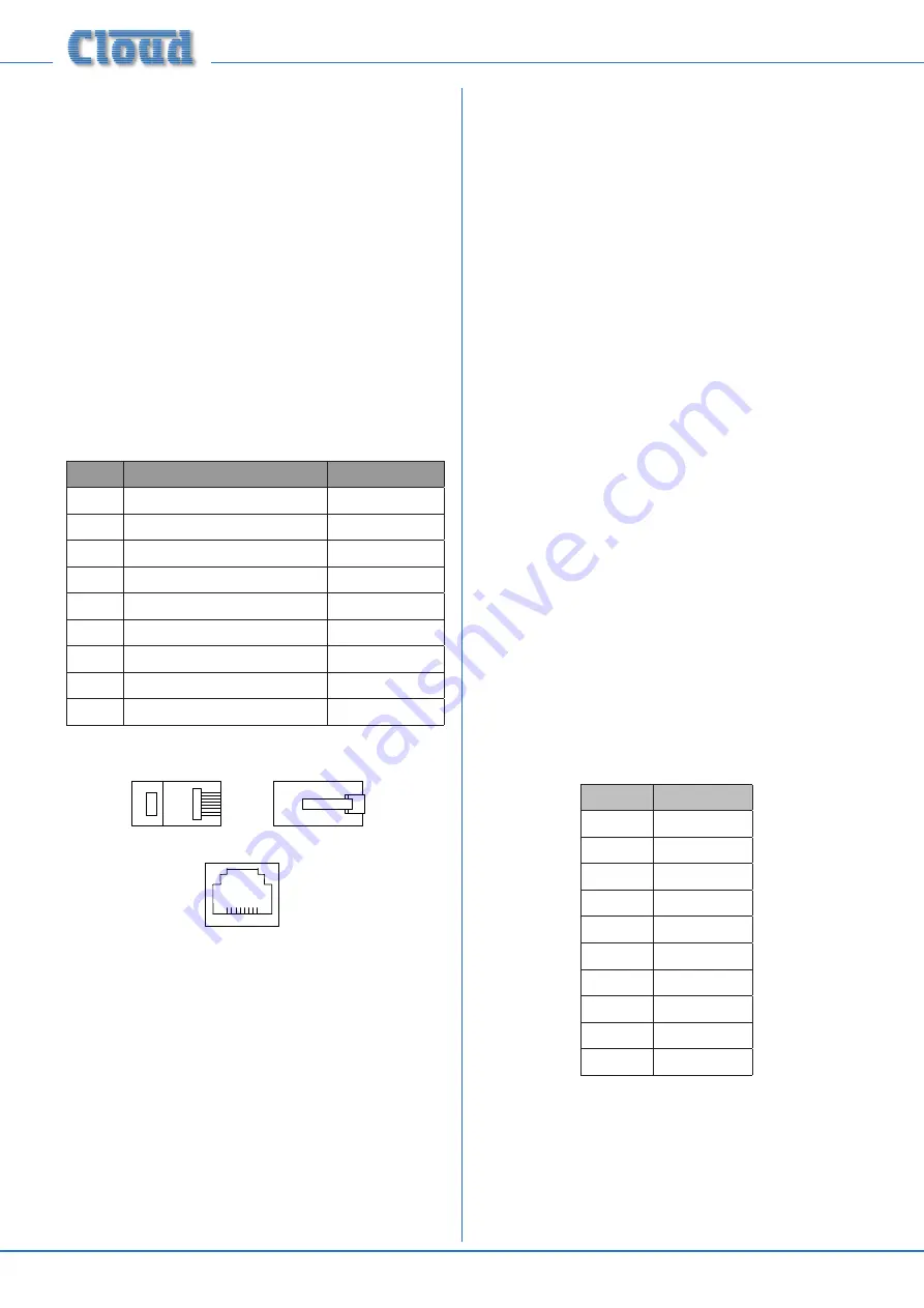
Each zone of the mixer is provided with a Facility Port in
the form of a rear panel 8-way RJ45 connector. The primary
use of the Facility Port is for the connection of LM-2 remote
active input modules, but it may also be used as a general-
purpose, per-zone auxiliary balanced input (see “Using the
Facility Ports as auxiliary zone inputs” on page 18 for more
information on this application). Note that audio connected
via a Facility Port will only appear at the same-numbered
Zone Output, and no other.
The active modules operate on DC power supplied by the
mixer. The current consumed by each module is minimal and in
the vast majority of installations there will be no power supply
issues. Nevertheless, installers are urged to check the data in
the Appendix regarding PSU capacity (see “PSU capability and
optional device current consumption” on page 24
).
The pinout of the Facility Port connector is given in the table
below:
PIN
USE
Cat 5 CORE*
1
Audio ‘cold’ phase (-)
White + Orange
2
Audio ‘hot’ phase (+)
Orange
3
Priority VCA control
White + Green
4
+ 15 V
Blue
5
0 V
White + Blue
6
-15 V
Green
7
Music level control (0 to 10 V)
White + Brown
8
Music source select control (0 to 10 V)
Brown
SCN
Screen for system music controls
Connector shell
* Standard wiring for pre-made cables
Please also refer to “LM-2 active input modules – general
considerations” on page 18 for further information
regarding installation of remote active input modules.
Connecting an LM-2 remote input module
The LM-2 should be connected to a Facility Port using
screened Cat 5 cable. (Note that as the cable carries analogue
audio,
only
screened Cat 5 should be used.)
All 8 cores are
used.
The LM-2 includes controls for local music level and
source selection, the wiring for these functions being catered
for on the Facility Port. Thus it is not necessary to make any
connections to the Zone’s Music Control Port
.
The LM-2’s upper PCB is fitted with an RJ45 connector
labelled OUTPUT. Connect this to the Facility Port of the
relevant Zone using screened Cat 5 cable with screened
RJ45s at each end. Follow the colour coding shown in the
previous table. The metal screening of the connectors should
be bonded to the screen of the cable. Full details can be found
in the LM-2 Installation Guide.
The second RJ45 connector on the LM-2, ‘LINK’, may be used
to “daisy-chain” additional LM-2s, thus allowing multiple input
modules to be installed at different locations in the zone. See
the LM-2 Installation Guide for more details.
Before the LM-2’s music source and level controls will operate,
set the MUSIC CONTROL push-button switch ([14] on page
9
) for the Zone where the LM-2 is installed to REMOTE
(i.e., pressing it in). In this setting, the Zone’s front panel Music
Level and Source Select controls become inoperative.
Sometimes it is desirable to permit remote control of music
level but keep music source selectable only on the mixer. In
this case, internal jumper J1 on the sub-board for the Zone in
use should be moved from ‘SW’ to ‘FR’. This will render the
LM-2’s music source switch inoperative, and return source
selection to the front panel. See page 22 for full details and
jumper locations.
Paging System connections
Cloud PM Series paging microphones may be connected
directly to the Z4
MK3
and Z8
MK3
.
Two connections are required: the paging mic audio signal
should be connected to the Paging Mic Input ([6] on page
9
) and the control cable to the 10-pin Zone Access port
). The pinout of the Zone Access port is
given below:
PIN NO.
FUNCTION
1
0 V
2
Zone 1
3
Zone 2
4
Zone 3
5
Zone 4
6
Zone 5
7
Zone 6
8
Zone 7
9
Zone 8
10
+15 V
Connecting a PM4/4SA/8/8SA/12/16 paging mic
These microphones are equipped with both digital and
analogue paging interfaces; the Z4
MK3
and Z8
MK3
use the
analogue interface. PM microphones are available in 4, 8,
12 or 16-zone versions; the installer should be sure he/she
understands how paging zones correspond to mixer zones
before commencing wiring.
Summary of Contents for Z4MK3
Page 26: ...Z4 8MK3 Installation and User Guide v1 2 26...
Page 27: ...Z4 8MK3 Installation and User Guide v1 2 27...
Page 28: ...Z4 8MK3 Installation and User Guide v1 2 28...
Page 29: ...Z4 8MK3 Installation and User Guide v1 2 29...
Page 30: ...Z4 8MK3 Installation and User Guide v1 2 30...


