M0G140F7-01 06/11/07
pag
20
8
1 2 3 4 5 6 7
CN2
12
10
9
11
16
+5
V
13
14
15
gn
d
19
17
18
21
20
SERIALE
TTL / RS485
CN
1
gn
d
12
V
A
C
+-
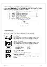
SERIAL CONVERTER TTL/RS485
OPTIONAL - code PE2N0002
Plugged-in in the main module on the electric board (see lay in the wiring diagram). It is
possible to connect up to 127 units with a single supervision system.
The connection with a PC must use a RS485/232 converter; the serial line RS232 can
be max. 10-m long.
CONNECTIONS:
make reference to the electrical panel and to the SIGNALS AND DATA LINES
paragraph
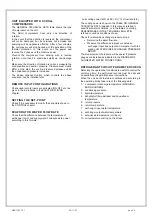
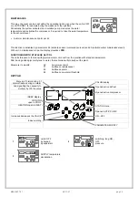
Below the indications for the serial connection ; refer anyway to the CLIVET “RS 485 NETWORKS – GUIDELINES”
document and ask for the COMMUNICATION PROTOCOL about the COMPACT-MEDIUM electronics
-
The total length of each single serial line, don’t
have to be over 1000 metres
-
The potential difference between the “ground” of
two RS485 switches must be less of 7 V
-
Couple of conductors twisted and shielded
-
Section of conductor 0.22mm
2
…0,35mm
2
-
Nominal capacity between conductors < 50
pF/m nominal impedance 120
Ω
-
Recommended cable BELDEN 3105 A
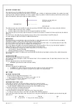
TYPE OF NETWORK
The serial lines must be connected in bus typology, i.e. nodes to more points are not admitted
OK
NO !
SHIELD
-
It must be connected to a ground without
disturbances
-
Connected to round in only one point
-
Provide to the shield continuity during all the serial
cable extension.
Sistema di supervisione
12 V AC
C
N
1
C
N
1
1
9
1
8
2
0
2
1
2
0
1
8
1
9
2
1
RS-485
RS-232
gnd
-+
Supervisor
TTL /
RS485
+
-
TO THE OTHER
UNITS
12 V AC
gnd
TTL /
RS485
-
gnd
+

