


M0G940E8-00 04/07/08
pag
17
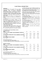
ELECTRICAL CONNECTION
GENERAL
The characteristics of the electrical lines and relevant
components must be determined by SPECIALIZED
PERSONNEL ABLE TO DESIGN ELECTRICAL
INSTALLATIONS; moreover, the lines must be in conformity
with professional procedures and the regulations in force.
All electrical operations should be performed by trained
PERSONNEL HAVING THE NECESSARY REQUISITES
UNDER LAW and being informed about the risks relevant to
these activities.
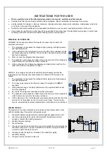
Before performing any operation on the electrical system,
make sure that the unit supply line is SELECTED AT
START.
The earth connection must be made prior to other electrical
connections.
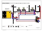
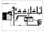
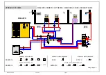
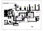
For all electrical type operations, REFER TO THE
ELECTRICAL DIAGRAM ATTACHED TO THE UNIT; the
number of the diagram is shown on the registration plate
positioned on the electrical board or next to it.
The electrical diagram should be carefully kept together with
this manual and should be AVAILABLE FOR FUTURE
INTERVENTION ON THE UNIT.
LINE OF UNIT POWER SUPPLY
The ELECTRICAL DATA OF THE UNIT are shown in the
technical chart of this manual and on the unit registration
plate. The presence of accessories can vary according to
the unit; the electrical data shown in the technical chart refer
to standard units. In the event of differences between the
data of the registration plate and the data shown in this
manual, as well as in the technical chart, please refer to the
DATA SHOWN IN THE REGISTRATION PLATE.
The protection device of the unit power supply line should
break off the short circuit power whose value should be
determined according to the plant features.
The section of supply cables and protection cable must be
seized according to the characteristics of the protections
used.
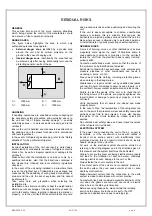
SIGNALS / DATA LINES
Do not overpass the maximum power allowed, which varies,
according to the type of signal.
Lay the cables far from power cables or cables having a
different tension and that are able to emit electromagnetic
disturbances.
Do not lay the cable near devices which can generate
electromagnetic interferences.
Do not lay the cables parallel to other cables; cable
crossings are possible, only if laid at 90°.
Connect the screen to the ground, only if there are no
disturbances
Assure the continuity of the screen during the entire
extension of the cable.
Observe, if any, the requirements about impendency,
capacity, attenuation
STANDARD UNIT ELECTRICAL DATA
VOLTAGE: 230/1/50
SIZE
21
31
41
51
F.L.A. FULL LOAD CURRENT AT MAX ADMISSIBLE CONDITIONS
F.L.A. - Pump
A
1,18
1,18
1,18
2,02
F.L.A. - Total
A
15,76
19,36
23,96
30,64
F.L.I. FULL LOAD POWER INPUT AT MAX ADMISSIBLE CONDITION
F.L.I. - Pump
kW
0,27
0,27
0,27
0,4
F.L.I. - Total
kW
3,5
4,3
4,9
6,9
M.I.C. MAXIMUM INRUSH CURRENT
M.I.C. - Value
A
63,26
84,26
99,26
133,64
power supply 230/1/50 Hz +/-6%
The pump is included in the total values calculation
for non standard voltage please contact Clivet technical office
The units are compliant with the provisions of European standards CEI EN 60204 and CEI EN 60335.
VOLTAGE: 400/3/50+N
SIZE
21
31
41
51
F.L.A. FULL LOAD CURRENT AT MAX ADMISSIBLE CONDITIONS
F.L.A. - Pump
A
1,18
1,18
1,18
2,02
F.L.A. - Total
A
7,1
9,2
9,9
13,9
F.L.I. FULL LOAD POWER INPUT AT MAX ADMISSIBLE CONDITION
F.L.I. - Pump
kW
0,27
0,27
0,27
0,4
F.L.I. - Total
kW
3,2
4
4,8
6,8
M.I.C. MAXIMUM INRUSH CURRENT
M.I.C. - Value
A
34,3
37,3
50,3
67,6
power supply 400/3/50 (+ NEUTRAL) +/- 6%
Maximum Phase Unbalance: 2%
The pump is included in the total values calculation
for non standard voltage please contact Clivet technical office
The units are compliant with the provisions of European standards CEI EN 60204 and CEI EN 60335.
Summary of Contents for WSAN-XPR 21
Page 2: ......
Page 25: ...M0G940E8 00 04 07 08 pag 25...
Page 48: ...M0G940E8 00 04 07 08 pag 48...
Page 49: ...M0G940E8 00 04 07 08 pag 49 TECHNICAL DATA...
Page 59: ......


