background image

22 

MSAT-XEE 8.2-30.2  

M09G60E14-04

Set the scheduling

1

set the scheduling num.1

scheduling 1 parameters

scheduling 2 parameters scheduling 3 parameters

1.1

set event 1

Event hour → par. tE10

Event minutes → par. tE11

Unit mode → par. tE12 (0=On, 1=standby)

tE38

tE39

tE40

tE66

tE67

tE68

1.2

set event 2

Event hour → par. tE17

Event minutes → par. tE18

Unit mode → par. tE19 (0=On, 1=standby)

tE45

tE46

tE47

tE73

tE74

tE75

1.3

set event 3

Event hour → par. tE24

Event minutes → par. tE25

Unit mode → par. tE26 (0=On, 1=standby)

tE52

tE53

tE54

tE80

tE81

tE82

1.4

set event 4

Event hour → par. tE31

Event minutes → par. tE32

Unit mode → par. tE33 (0=On, 1=standby)

tE59

tE60

tE61

tE87

tE88

tE89

2

set the scheduling num.2

column → scheduling 2 parameters

3

set the scheduling num.3

column → scheduling 3 parameters

4

assign the scheduling to monday

tE01 = 1 scheduling 1

= 2 scheduling 2

= 3 scheduling 3

5

assign the scheduling to tuesday

tE02 = 1 scheduling 1

= 2 scheduling 2

= 3 scheduling 3

6

assign the scheduling to wednesday

tE03 = 1 scheduling 1

= 2 scheduling 2

= 3 scheduling 3

7

assign the scheduling to thursday

tE04 = 1 scheduling 1

= 2 scheduling 2

= 3 scheduling 3

8

assign the scheduling to friday

tE05 = 1 scheduling 1

= 2 scheduling 2

= 3 scheduling 3

9

assign the scheduling to saturday

tE06 = 1 scheduling 1

= 2 scheduling 2

= 3 scheduling 3

10

assign the scheduling to sunday

tE07 = 1 scheduling 1

= 2 scheduling 2

= 3 scheduling 3

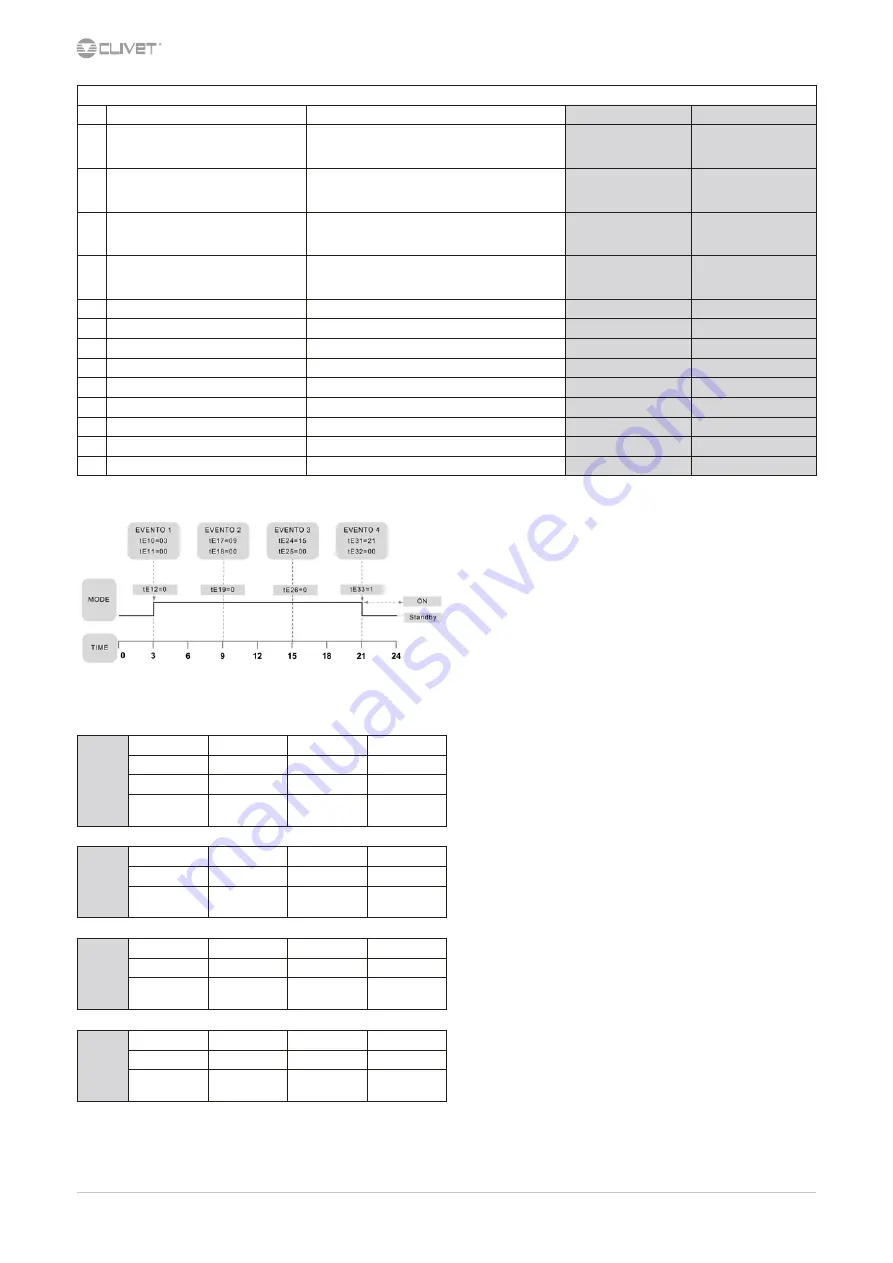
Example: scheduling 1

Events parameters

Event 1

Sched. 1 (par.)

Sched. 2 (par.)

Sched. 3 (par.)

Time

tE10

tE38

tE66

Minutes

tE11

tE39

tE67

Mode 0= on

1= standby

tE12

tE40

tE68

Event 2

Time

tE17

tE45

tE73

Minutes

tE18

tE50

tE74

Mode 0= on

1= standby

tE19

tE47

tE75

Event 3

Time

tE24

tE52

tE80

Minutes

tE25

tE53

tE81

Mode 0= on

1= standby

tE26

tE54

tE82

Event 4

Time

tE31

tE59

tE87

Minutes

tE32

tE60

tE88

Mode 0= on

1= standby

tE33

tE61

tE89

Summary of Contents for MSAT-XEE 10.2

Page 1: ...M09G60E14 04 11 07 17 Installation and operating manual Air cooled condensing unit for outdoor installation MSAT XEE 8 2 30 2...

Page 2: ...he installation and maintenance cost for the life cycle of the system The purpose of this manual is to provide you with information that is useful from reception of the equipment through installation...

Page 3: ...Reception 6 3 Positioning 8 4 Refrigeranting connections 9 5 Electrical connections 12 6 Start up 14 7 Control 17 8 Maintenance 25 9 Decommissioning 28 10 Residual risks 29 11 Dimensional drawings 30...

Page 4: ...arried out by inexperienced personnel they may cause damages to things and injuries people 1 4 Intended use Use the unit only for air conditioning Keep to the limits foreseen in the technical schedule...

Page 5: ...n case of breakdown or malfunction Immediately deactivate the unit Contact a service centre authorized by the manufacturer The installer must train the user particularly on Start up shutdown Set point...

Page 6: ...ceipt to supplier and the carrier Any disputes must be made within 8 days from the date of the delivery Complaints after this period are invalid 2 1 Storage Observe external packaging instructions 2 2...

Page 7: ...EE 8 2 30 2 7 2 3 Packaging removing Be careful not to damage the unit Keep packing material out of children s reach it may be dangerous Recycle and dispose of the packaging material in conformity wit...

Page 8: ...ll bearing points are aligned and leveled install the unit raised from the ground max distance allowed by the electrical connections Prefer places where the unit doesn t disturb the neighbours Avoid i...

Page 9: ...nitrogen or dry air before connecting the pipes to the two units and without humidity to allow a good vacuum operation The installation of the pipes may affect the level of noise in the system instal...

Page 10: ...riable climatic conditions for example fresh air temperature with ranges day night summer winter The receiver must have a capacity adequate to the installation and it must be positioned near the evapo...

Page 11: ...frigerant gas tank venting the air out of the hose for connection to the gauge group Open the tap of the liquid line Open the taps of the gauge group and let liquid state refrigerant enter using an ap...

Page 12: ...input at max admissible condition Electrical wiringdiagram Nr 5 2 Connections 1 Refer to the unit electrical diagram the number of the diagram is shown on the serial number label 2 Verify that the el...

Page 13: ...customer ALM Cumulative fault signal max 24v AC QS1 Isolating switch XT1 Terminal block of the customer connections QG Electrical panel SA2 Compressor 1 request 5 6 RCTX Remote control For details see...

Page 14: ...ks For details refer to the different manual sections Unit OFF power supply 1 safety access 2 functional spaces 3 refrigerant line section 4 length of the refrigerant lines 5 height difference in the...

Page 15: ...acharge temperature WARNING BURN DANGERI 2 Condensation pressure 3 Liquid temperature 4 Dehydrator filter upstream and downstream temperature 5 Return pressure 6 Return temperature 7 Fresh air tempera...

Page 16: ...the following data total voltages and absorptions with unit at full load absorptions of the different electric loads compressors fans pumps etc temperatures and flows of the different fluids water ai...

Page 17: ...ssor 2 On fixed Not used 7 2 Keys Symbol Name Action Function 3 sec Up Increases the value Next voice Silenced alarm Down Decreases the value Previous voice On Standby Esc Esc WITHOUT SAVING MODIFICAT...

Page 18: ...eset St on off CC copy card EUr alarm log reset PASS password EU alarms Alarm log 7 5 ON OFF OFF Emergency stop drive stops immediately without observing any timing Step Display Action Keys Menu Varia...

Page 19: ...u Ai analogical inputs digital di digital inputs AO analogical outputs dO digital outputs 3 of Access diL1 4 diL1 Scroll the list Choose diL4 5 diL4 Press to see the value For digital inputs 0 input n...

Page 20: ...r Select FnC 3 FnC Press dEF 4 dEF Select tA 5 tA Press 6 Press Back to the previous menu 7 12 Alarm log Before resetting an alarm identify and remove its cause Repeated resets can cause irreversible...

Page 21: ...thermoregulation Thermoregulation St Stati Operating modes Operating stata CP ComPressori Compressor PI Pump Internal Primary circuit water pump FI Fan Internal Not used FE Fan External Fans external...

Page 22: ...onday tE01 1 scheduling 1 2 scheduling 2 3 scheduling 3 5 assign the scheduling to tuesday tE02 1 scheduling 1 2 scheduling 2 3 scheduling 3 6 assign the scheduling to wednesday tE03 1 scheduling 1 2...

Page 23: ...emperature The probe is not used to perform the ambient thermoregulation Follow these steps Step Display Action Keys Menu Variable Notes 1 Main menu Press PAr 2 PAr Press PAr 3 PAr Select Cr 4 Cr Pres...

Page 24: ...Press Ui 5 Ui Select Ui22 6 Ui22 Confirm 0 7 0 Select 1 8 1 Confirm 1 9 Press Back to the previous menu Step Display Action Keys Menu Variable Notes 1 Main menu Press 3 sec 2 Select Air1 3 Air1 Press...

Page 25: ...a unit booklet to take notes of the unit interventions In this way it will be easier to adequately note the various interventions and aid any troubleshooting Report on the booklet date type of interv...

Page 26: ...l device test alarm signalling thermometers probes pressure gauges etc X European regulation 303 2008 Refer to the local regulations and ensure correct adherance Companies and technicians that effect...

Page 27: ...27 8 9 Electric fans Check the fans and the relative protection gridsare well fixed the fan bearings evident by noise and anomalous vibrations the terminal protection covers are closed and the cable h...

Page 28: ...vered by the legislation in question are marked with the symbol on the side With the aim of protecting the environment all of our units are produced in compliance with Directive EC on waste electrical...

Page 29: ...Periodically check that all of the panels are correctly closed and fixed If there is a fire the temperature of the refrigerant could reach values that increase the pressure to beyond the safety valve...

Page 30: ...d line piping d 16 mm 8 suction line piping d 28 mm 9 Main isolator switch 10 vibration mounts position 11 lifting holes position Size 8 2 10 2 12 2 A Length mm 1739 1739 1739 B Width mm 721 721 721 C...

Page 31: ...d 16 mm 8 suction line piping d 28 mm 9 Main isolator switch 10 vibration mounts position 11 lifting holes position Size 16 2 18 2 22 2 A Length mm 1197 1197 1197 B Width mm 1143 1143 1143 C Height mm...

Page 32: ...line piping d 16 mm 8 suction line piping d 28 mm 9 Main isolator switch 10 vibration mounts position 11 lifting holes position Size 26 2 30 2 A Length mm 2367 2367 B Width mm 1141 1141 C Height mm 15...

Page 33: ...pressure level 1 m 3 dB A 60 60 60 64 64 65 65 65 Dimensions A Length mm 1739 1739 1739 1967 1967 1967 2367 2367 B Width mm 721 721 721 1143 1143 1143 1141 1141 C Height mm 1287 1287 1287 1599 1599 1...

Page 34: ...2 Operating range with modulating fans 3 Operating range with option Min outdoor temperature 15 C MEN15 4 Operating range with option Min outdoor temperature 30 C MEN30 SST saturated suction temperatu...

Page 35: ...monitor INSTALLATION AMMX Rubber antivibration mounts PGCEX Coil protection grilles outdoor air side Various MEN30 Minimum outdoor air temperature down to 30 C MEN15 Minimum outdoor air temperature do...

Page 36: ...2 M09G60E14 04 13 1 RCTX Remote control QG Electrical panel XT1 Terminal block of the customer connections AP7 Room keypad A Max 100 mt Cable section Min 0 35 Max 1 mm2 The cable must be shielded LAN...

Page 37: ...he function Par CF01 protocol selection 0 Disabled 1 Modbus Parameter modification Main menu Parameters CF CF01 Parameter Description Range CF30 address Modbus 1 255 CF31 BaudRate Baud Rate 0 1200 1 2...

Page 38: ...the assembly of an LG mixer tap on the evaporator a CPCF valve on the condensing unit an additional connection pipe for the bypassed hot gas Condensing unit COND Condenser CPCF Hot gas by pass valve...

Page 39: ...high pressure input circuit AUTO E080 Configuration error AUTO E081 Signalling of compressor operating hour exceeding Manual E090 Signalling of alarm log record exceeding Manual A AUTOMATIC reset M M...

Page 40: ...sor 1 start dO L2 Compressor 2 start dO L3 Fan start dO L4 Not used dO L5 Not used dO L6 Cumulative alarm E1 1rE1 Not used 1rE2 Not used 1rE5 Not used 1rE6 Not used 1rE7 Not used 1SP4 Not used Sr Not...

Page 41: ...43 Letter Seite...

Page 42: ...Madrid Espa a Tel 34 91 6658280 Fax 34 91 6657806 info clivet es CLIVET GmbH Hydronic and Applied Division Hummelsb tteler Steindamm 84 22851 Norderstedt Germany Tel 49 0 40 32 59 57 0 Fax 49 0 40 32...

Reviews: