background image


13

3.1  Tool Assembly 


Only use NORTON CLIPPER continuous rim blades with a maximum diameter of 7” 

(177mm) can be used with the CTC701.  All tools used must be selected with regard to 

their maximum permitted cutting speed for the machine’s maximum permitted rotation 

speed.  Before mounting a new blade into the machine, switch off the machine and 

isolate it from the main source of electricity. 


3.2  Installing The Blade 


  Loosen the two screws on the side of the plate blade cover with the 

Phillips head screw driver and remove the plate blade cover.  

  Loosen the hexagonal nut which holds the removable outer flange on 

the blade shaft with the 19mm wrench and use the spanner wrench to 
lock the flange.  

  Remove the outer flange.  

  Loosen the two screws holding the blade guard support and remove it from the 

machine.  

  Clean the flanges and blade shaft and inspect for wear.  

  Mount the blade on the flange ensuring that the direction of rotation is correct 

(check with the arrow on the blade guard for blade shaft rotational direction and 
match the blade rotational direction to the machine).  Installing the blade 
incorrectly can cause poor cutting performance and reduce the life of the blade. 

  Replace outer blade flange.  

  Tighten hexagonal nut.  


Retighten the two screws holding the front cover, and reassemble the blade 
guard support on the table. The blade bore must correspond exactly to the 
diameter of the blade shaft. Cracked or damaged bore is dangerous for the 
operator and for the machine


3.3  Guide-A-Cut Assembly 


To assemble the guide a cut:  

  Put the guide a cut on the table.  

  Use the handle on the side of the guide-a-cut to pinch it on the table  


3.4  Electrical Connections 


Check that,  

  The voltage/phase supply corresponds to the information indicated on the motor 

plate.  

  Available power supply must have ground connection in conformity with safety 

regulations.  


3.5  Starting The Machine 


Press the green button to start the machine. Press on the red button to stop the 

machine. The red button is also the emergency switch. 
 

3.6  Water Cooling System 


Plate Blade Cover

Summary of Contents for CTC701

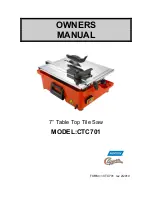
Page 1: ...OWNERS MANUAL 7 Table Top Tile Saw MODEL CTC701 FORM CTC701 rev 2 2010...

Page 2: ...or incidental damages arising out of the failure of any product to operate properly Integral units such as gasoline engines electric motors batteries tires transmissions etc are excluded from this wa...

Page 3: ...he Machine 13 14 3 6 Water Cooling System 4 Transport And Storing 14 4 1 Securing For Transport 14 4 2 Long Period Of Inactivity 14 5 Operating the CTC701 14 15 5 1 Positioning The CTC701 14 5 1 2 Spa...

Page 4: ...ate the machine s warranty The Saint Gobain Abrasives Inc shall not be held responsible for any resulting damage Any risk shall be borne entirely by the user Observing the operating instructions and c...

Page 5: ...ny piece of equipment Keep hands feet hair and clothing away from all rotating parts Never tamper with the governor components of settings to increase the maximum speed Severe personal injury and dama...

Page 6: ...t warnings and instructions for the safe and effective use of the material being cut California and some other authorities for instance have published lists of substances known to cause cancer reprodu...

Page 7: ...damaged or badly worn blades as any damaged or badly worn blade is a danger to the operator The material to be cut must be held securely in place on the table to allow no unexpected movement during cu...

Page 8: ...se the cord Never carry the tool by the cord or yank the cord to disconnect the plug from the receptacle ALWAYS disconnect the power before servicing or changing accessories or Diamond Blades ALWAYS m...

Page 9: ...the blade 6 Fill the water pan with water 7 The blade guard must be in place with the nose guard down and locked when the saw is running 8 The operator should wear safety glasses and any other approp...

Page 10: ...immediately appreciate the attention given to detail and quality of materials used in construction The machine and its component parts are assembled to high standards assuring long life and minimum ma...

Page 11: ...miter cuts To tilt the cutting table loosen the two screws on the side and pivoting the table The CTC701 has a built in gauge for precise angle adjustments Guide a cut 5 The guide a cut can be adjust...

Page 12: ...n mm 18 11 460mm Saw Width in mm 14 17 360mm Saw Height in mm 11 7 16 290 Weight Crated lbs kg 40 lbs 18 kg Weight uncrated lbs kg 35 lbs 15 9 kg Weight Of Machine With Water Pan Full 41 lbs 19 kg Sou...

Page 13: ...tion is correct check with the arrow on the blade guard for blade shaft rotational direction and match the blade rotational direction to the machine Installing the blade incorrectly can cause poor cut...

Page 14: ...at a constant temperature 5 Operating the CTC701 5 1 Positioning The CTC701 Remove anything from the area which might hinder the working procedure Make sure the site is sufficiently well lit Observe...

Page 15: ...ake sure the water tray contains enough water Set the guide a cut to the desired width of cut using the two engraved measurements to align it correctly Do not force on the motor This machine is not de...

Page 16: ...No Electricity Check The Electrical Supply Circuit Breaker For Example Extension Cable Is Too Small Of Gauge Or Too Long Change Extension Cable Do Not Exceed A 50 10AWG Defective Extension Cable Chan...

Page 17: ...nd technical support obtained from your local distributor where machines spare parts and Norton Diamond Blades can be purchased as well For the nearest Clipper distributor call 1 800 554 8003 Common R...

Page 18: ...18 8 1 CTC701 Service Parts...

Page 19: ...BRACKET SWITCH CTC701 1 S 23 243020 00310361104 CABLE GUIDE 1 W 24 243021 POWER CABLE CTC701 1 W 25 243022 SECURING STRAP POWER CABLE CTC701 6 S 26 243023 SCR M4 X 13 7 S 27 243024 PLATE HANDLE SUPPOR...

Page 20: ...ADE COVER CTC701 1 S 74 235103A 70184600881 SCR M5 X 12 0 8 DIN933 2 S 75 243069 70184641855 DRAIN PLUG CTC701 1 W 76 243070 70184641854 WATER PAN CTC701 1 S 77 235065 70184600790 WASHER M5 DIN125 FLA...

Page 21: ...21 NOTES...

Page 22: ...22 Saint Gobain Abrasives 2770 West Washington Stephenville TX 76401 Phone 800 554 8003 Fax 800 443 1092...

Reviews: