background image

18

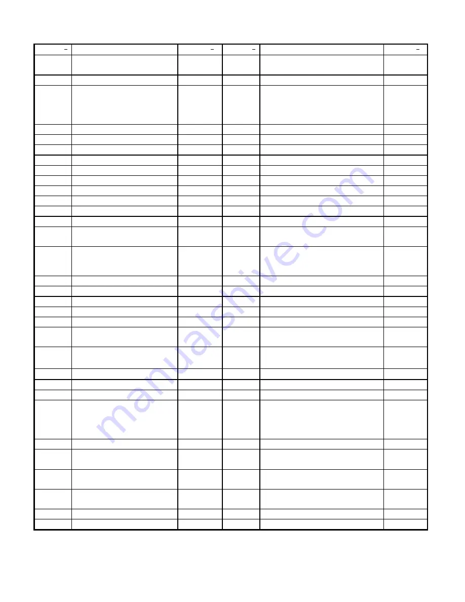
BBH Masonry Saw Parts

Item N

o

Description

Part N

o

Item N

o

Description

Part N

o

1

Drain Plug

213622

33

Lower Stay Level Arm
Assembly

219074

2

Frame Weldment

219026C

34

Bearing Kit Pivot Head

219070

3

Water Pump Kit
Screen
Hood
Impeller (Not Shown)

216138
216641
216642
216658

35

Water Curtain Assembly

219038

4

Conveyor Cart

216286

36

Protection Plate Kit

218047

5

Sheaves, Cart [4]

213621

37

Bushing Bearing Nylon

213631

6

Back Stop, Cart

216288

38

Support Blade Shaft

214129C

7

Wood strip, Cart

216287

39

Bearing Blade Shaft (1)

218049

8

Hardware Kit, Back Stop

216293

40

Blade Shaft Kit

218050

9

Guide A Cut Assembly

216128

41

Loose Collar

218016

10

Scale Kit

216291

42

Screw Loose Collar

8042096

11

Wrench 3/4"

213643

43

Belt Guard Assembly

218051

12

Wrench 7/8"

214124

44

Pulley Blade Shaft

76132

13

Stop Rubber

210051

45

Bracket Belt Guard

218052

14

Tensioning Eye-Bolt

73277

46

V-Belts 20” Blade Guard
V-Belts 14” Blade Guard

216662
216663

15

Spring, Foot Pedal

72567

47

Pulley Motor 14”  5HP
Pulley Motor 20” 5HP
Pulley Motor 20” 7.5HP

76130
76131
210926

16

Decal Kit (Not Shown)

219062

48

Screw Belt Tensioning

73277

17

Raising Screw Assembly

219063

49

Cutting Head Weldment

219015C

18

Raising Screw Kit

219064

50

Clamp Kit Cable

214029

19

Hand Wheel

219034

51

Stay Level Pivot Weldment

219009

20

Set Collar

101132

52

Splash Guard Kit

218053

21

Bearing Kit Raise Screw

219065

53

Blade Guard 14”
Blade Guard 20”

214102C
218007

22

Cover, Raise/Lower

219010

54

Water Distribution Assy. 14”
Water Distribution Assy. 20”

214052
218055

23

Foot Pedal Weldment

219029

55

Cam Kit Stay Level Arm

214132

24

Horizontal Link

219031

56

Stay Level Arm

218014

25

Drain Hose & Clamp

219066

57

Pin Kit Stay-Level Arm

214131

26

Vertical Link Assembly

219067

58

Motor 5HP 230/60Hz/1ph
Motor 5HP 230-460/60Hz/3ph
Motor 7.5HP 230-
460/60Hz/3ph

211038
219040
219041

27

Diagonal Link Weldment

219032

59A

Receptacle Water Pump

212168

28

Yoke Weldment
Assembly

219068

59B

Pigtail Water Pump

212168

29

Connecting Link
Assembly

219069

60

Switch Assembly 230/60/1
Switch Assembly 230-460/60/3

218093
218094

30

Pivot Bar Rear

219071

-NA-

Switch Box Only (NO
SWITCH)

219060

31

Swing Arm Assembly

219072

-NA-

Electrical Switch & Box Only

219059

32

Set Collar Kit

219073

Summary of Contents for BBH255

Page 1: ...OWNERS MANUAL Clipper Masonry Saw Models BBH455 BBH255 BBH275 FORM 5316 rev9 00 ...

Page 2: ...uction Products be liable for consequential or incidental damages arising out of the failure of any product to operate properly Integral units such as gasoline engines electric motors batteries tires transmissions etc are excluded from this warranty and are subject to the prime manufacturer s warranty This warranty is in lieu of all other warranties expressed or implied and all such other warranti...

Page 3: ...Use Step Cutting With Abrasive Blades 10 D How To Use Jam Cutting And Step Cutting With Diamond Blades 11 E How To Use For Dry Cutting 12 F How To Use For Wet Cutting 12 III Maintenance 13 15 A V Belts 13 B Motor 14 C Blade Shaft Bearings 14 15 D Pump 15 IV Parts List 16 34 A Ordering Information 16 B Parts List 17 18 C Power Unit Service Center Information Service Center Listing 16 19 26 ...

Page 4: ...e water pump and water pump bracket from carton Clip water pump bracket to rear of pan and insert water pump into bracket 5 Connect electrical outlet from water pump to electrical outlet rear of motor 6 Attach water hose to water pump Route water hose by passing hose behind pivot bar 7 Remove the conveyor cart and guide from the carton and install on the pan 8 Remove the drain plug from the carton...

Page 5: ...an extension cord with an electrical plug with 30 amp minimum capacity may be used Connecting wires should be as short as possible and in one piece In no case should the connecting wires be longer than shown in the following table for 5 h p single phase motors Length Of Wire Wire Gauge 3 5 HP 230v 1PH 5HP 230 460v 3HP 7 1 2HP 230 460v 3HP 12 50 NA NA 10 100 70 NA 08 150 110 140 06 NA 180 200 Cauti...

Page 6: ...5 I PEPARATION C Wiring Diagram ...

Page 7: ...6 ...

Page 8: ...ainst the outside blade shaft collar be sure to tighten enough to hold the blade firmly without slipping but do not over tighten 4 Adequate coolant must be used for wet cutting abrasive and diamond blades 5 The blade must be operated within the specified maximum operating speed 6 The operator should wear safety glasses ear plugs dust mask and any other appropriate safety equipment 7 When starting ...

Page 9: ...ter it is turned off Never operate the engine with any heat shields or guards removed Keep all guard in place when operating any piece of equipment Keep hands feet hair and clothing away from all rotating parts Lethal Exhaust Gas use only in well ventilated areas Engine exhaust gases contain poisonous carbon monoxide which is order less colorless and can cause death if inhaled Avoid inhaling exhau...

Page 10: ...ause to run out of alignment causing excessive blade wear When tightening bolt against outside blade shaft collar be sure to tighten enough to hold the blade firmly without slipping but do not over tighten excessive tightening can cause fracture of abrasive blades Using blade shaft wrench in bracket remove the blade shaft bolt and loosen collar Place the blade on the arbor and attach the loose col...

Page 11: ... the backward stroke Complete each rapid stroke backward and forward by passing the material beyond the center of the blade before starting the reverse movement of the cart The harder the material the more rapid the forward and backward strokes 3 Step cutting as can be seen in the sketch below lessens the area of the blade circumference in contact with the material keeping the blade cool running f...

Page 12: ...isted off 4 Do not force the material or bump into the blade When nearing completion of the cut retard and slightly hold back the conveyor cart If this is not done the material may be pulled into the blade so fast that excessive pressure on the rim may cause warping or twisting of the rim section 5 When a new diamond blade is broken in make the first few cuts slowly until the blade cuts freely and...

Page 13: ... from pan and submerge it in water barrel Remove the drain plug so the used water and sludge will drain from pan 1 Prepare water supply 2 Install water curtain on cutting head pivot bar 3 Be sure the water pump is plugged into the receptacle on the back of the masonry saw motor The pump will start when the main switch is turned on 4 Handle on petcock should be turned in line with the water flow St...

Page 14: ...t the belts Then impose the peak load If the belts slip tighten them until they no longer slip at peak load 3 Remember too much tension shortens belt and bearing life 4 Check belt tension frequently during the first day of operation Check belt tension periodically thereafter and make any necessary adjustments 5 The two most common causes of misalignment are shown in the drawing a The engine drive ...

Page 15: ...re daily relubrication under normal conditions However to assure long life the bearings do need to be relubricated periodically The time interval between greasing is dependent on the running speed and operating conditions The following chart covers most situations and can be used as a guide Temperature Cleanness Greasing Interval Up To 150 F Dirty 6 to 12 Months Over 150 F Dirty Daily to 2 Weeks A...

Page 16: ...t Size Maximum Grease Capacity of Bearing Chamber In Ounces 7 8 to 1 3 16 1 4 D Pump The submersible pump is equipped with a thermal overload protector and the sealed bearings require no relubrication The pump is designed to run wet or dry but for continued dry cutting disconnect the pump 1 Be sure to keep the pump clean do not allow sediment to cake in the pump and clog it 2 Keep all lines clean ...

Page 17: ...ment inspect the part you have and provide additional description as necessary 4 Specify mode of shipping desired for example parcel post truck air freight U P S best way etc B Parts List See assembly drawing C Power Unit Service Information Repair or replacement service is available from your nearest authorized service station Refer to the service center listing for the nearest authorized motor e...

Page 18: ...17 V PARTS LIST SECTION D Assembly Drawing ...

Page 19: ...HP Pulley Motor 20 7 5HP 76130 76131 210926 16 Decal Kit Not Shown 219062 48 Screw Belt Tensioning 73277 17 Raising Screw Assembly 219063 49 Cutting Head Weldment 219015C 18 Raising Screw Kit 219064 50 Clamp Kit Cable 214029 19 Hand Wheel 219034 51 Stay Level Pivot Weldment 219009 20 Set Collar 101132 52 Splash Guard Kit 218053 21 Bearing Kit Raise Screw 219065 53 Blade Guard 14 Blade Guard 20 214...

Page 20: ...19 ...

Page 21: ...20 ...

Page 22: ...21 ...

Page 23: ...22 ...

Page 24: ...23 ...

Page 25: ...24 ...

Page 26: ...25 ...

Page 27: ...26 ...

Page 28: ...27 NOTES ...

Page 29: ...28 Norton Construction Products PO Box 2898 Gainesville GA 30503 Phone 800 554 8003 or 770 967 3954 8 00 A M to 7 00 P M Eastern Time Fax 800 443 1092 or 770 967 7287 ...

Reviews: