


34
G e o t h e r m a l H e a t i n g a n d Co o l i n g
Trilogy
®
Variable
(VE) Series IOM - 60Hz HFC-410A
R e v i s i o n D a t e : 2 2 D e c e m b e r, 2 0 2 1
System Configuration
Configuring The iGate
®
Connect Thermostat
The first step after installing the iGate
®
Connect thermostat is
to configure the settings for the various devices that are being
connected. This can be done through the myUplink App or
Service Tool. The various configuration options are detailed
below and in the iGate Connect IOM.
The Unit Configuration settings allow the installer to configure
the thermostat to the installed equipment.Unit Configuration
is only necessary when replacing a unit controller. The Unit
Configuration settings are programmed at the factory when
the unit is built.
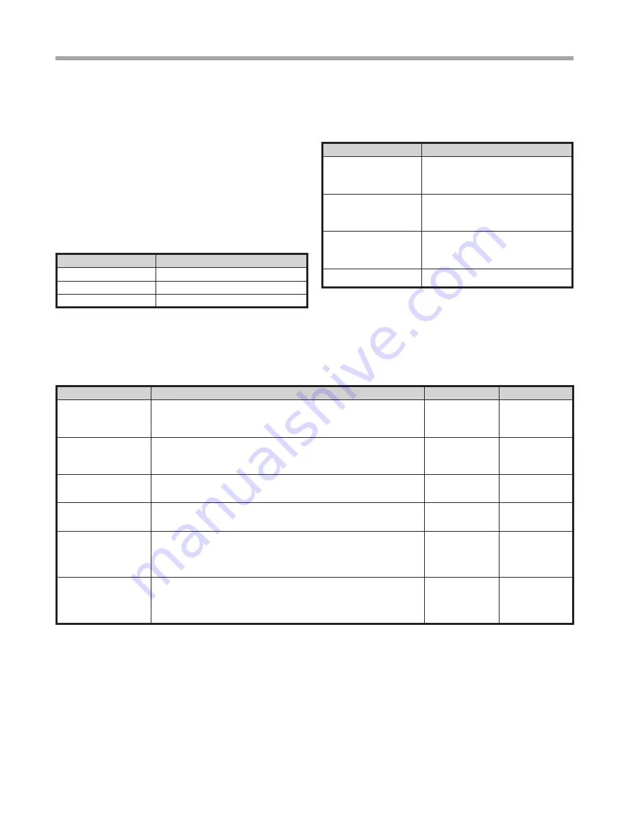
Configuration Setting
Description
Heat Pump Family
Select the family of heat pump.
Heat Pump Size
Select the unit model.
Blower Type
Select the blower type.
Capacity Configuration
Range for the capacity settings will depend on model selection.
Configuration Setting
Description
Minimum Heating Capacity
Configures the minimum unit heating
capacity. When the space requires a
heating capacity below this setting the unit
will cycle off.
Maximum Heating
Capacity
Configures the maximum unit heating
capacity. When the space requires a
heating capacity above this setting the unit
will call for auxiliary heat (if applicable).
Minimum Cooling Capacity
Configures the minimum unit cooling
capacity. When the space requires a
cooling capacity below this setting the unit
will cycle off.
Maximum Cooling
Capacity
Configures the maximum operational unit
cooling capacity.
Threshold Configuration
This section configures the temperature, time, and capacity thresholds associated with the heating, cooling, and hot water (if
applicable) equipment. You must configure the Equipment settings before setting the thresholds. Only the applicable threshold
settings will be displayed.
System Setting
Description
Range/Options
Default
Compressor Anticipator
Configures the sensitivity of the thermostat to the space temperature. A
lower setting will cause the unit to respond more rapidly to changes in space
temperature. A higher setting will cause the unit to respond more slowly to
changes in space temperature.
1 to 10
5
Cooling Hot Water
Cut Out
Determines the point at which the space cooling demand outpaces the ability of
the potable water heating mode to accept the heat of rejection from the cooling
mode when both are active at the same time. At this setting and above the heat
of rejection from the cooling mode will be sent to the source (ground loop).
70% to 100%
100%
Heating Hot Water
Cut Out
Potable water heating normally takes priority over space heating. This setting
determines the point at which the space heating demand will take priority over
the potable water heating demand.
70% to 100%
90%
Auxiliary Heat Dead-Band
Configures the amount of space temperature droop allowed from the heating
setpoint at maximum unit capacity before allowing auxiliary heat for space
heating.
0.0°F to 5.0°F
1.0°F
Cooling Hot Water
Cut Out Offset
This setting establishes the maximum acceptable space temperature rise
during the cooling mode while the heat from the space is being rejected into
the potable hot water. If the space temperature rises more than this amount,
the potable water heating mode will be terminated and the cooling mode will
reject the heat from the space to the source (ground loop).
0.5°F to 1.5°F
0.5°F
Heating Hot Water
Cut Out Offset
This setting establishes the maximum acceptable space temperature drop
during the potable hot water mode before the unit switches to the space
heating mode. If the space temperature drops more than this amount, the
potable water heating mode will be terminated and the space heating mode will
be activated.
0.5°F to 1.5°F
1.0°F